


For servo vs stepper CNC selection, start with the same axis speed, load, acceleration and control-interface profile rather than the motor name. A stepper-style step/direction path can fit many CNC jobs when the controller can deliver the required pulse timing, while a servo-style path becomes easier to justify when the project needs encoder feedback, PID-style loop integration and diagnostic visibility.
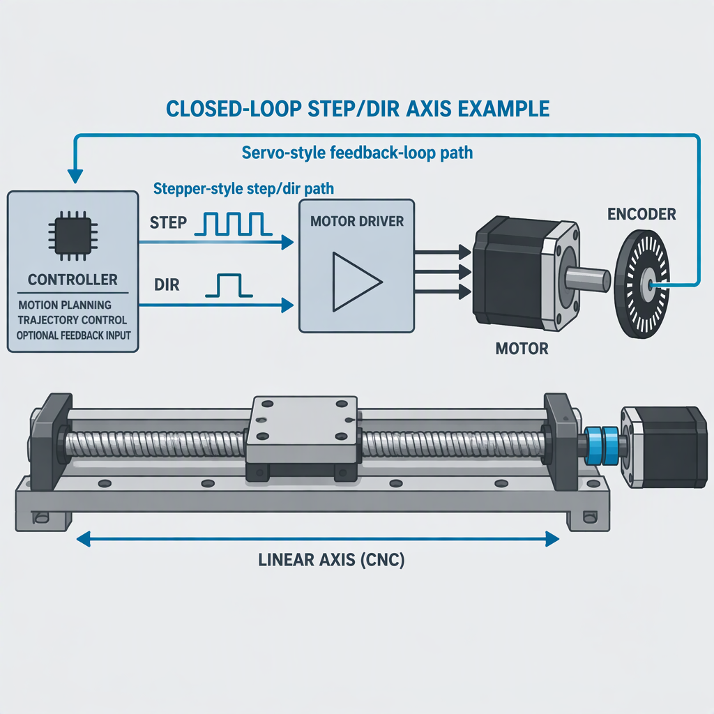
Compare servo and stepper CNC axes under the same conditions
A fair comparison keeps the mechanical load case fixed, then compares the motion path: timed step-pulse generation on one side and feedback-loop control architecture on the other.
Stepper-style path
Use this path when the CNC controller, drive and axis scaling can meet the required step/direction timing, velocity limit and acceleration limit for the job.
Servo-style path
Use this path when the application needs encoder feedback, a closed-loop control element such as a PID loop, and more diagnostic signals for commissioning and fault analysis.
| Selection factor | Stepper-style CNC path | Servo-style CNC path |
|---|---|---|
| Controller signal | Plan step/direction output, timing parameters and position scaling. | Plan feedback signals and loop-control components as part of the axis architecture. |
| Speed check | Confirm that the pulse generator can support the requested step rate for the selected scaling. | Confirm that feedback counting and loop timing support stable control at the target profile. |
| Buyer risk | The axis can be limited by control pulse rate before the motor catalog appears to be the limit. | The axis can require more tuning discipline because feedback and loop behavior become part of the purchase decision. |
For a retrofit or new machine, do not compare a low-resolution stepper setup against a fully tuned servo axis and call it a motor comparison. Compare both candidates using the same screw pitch, gearing, axis mass, duty cycle, target feedrate, acceleration target, controller update environment and acceptance test.
Check speed through the control interface, not only the motor catalog
A CNC stepper setup can become speed-limited by pulse-generation capacity, so the required steps per unit and target velocity must be checked against the controller’s practical step-rate capability.
LinuxCNC’s STEPGEN documentation describes software step pulse generation for stepper motors and notes that maximum step rate depends on CPU and other factors, with hardware step generation recommended when higher rates are needed.
- Calculate position scale from motor steps, microstepping or electronic gearing, transmission ratio and machine travel.
- Compare the resulting pulses per second with the controller’s practical step-generation range for the chosen control platform.
- Check drive timing requirements such as step length, step spacing, direction setup and direction hold.
- Confirm that acceleration and velocity limits are applied in the motion configuration, not assumed from the motor label.
For high-resolution axes, the control-interface calculation can change the decision. A stepper motor with enough static torque may still be the wrong fit if the commanded resolution pushes the controller beyond reliable pulse timing at the required feedrate.
Match load, acceleration and feedback to the axis job
Load and acceleration should be evaluated as a complete axis profile because the control setup must respect velocity limits, acceleration limits, position scaling and feedback strategy.
| Axis condition | Selection boundary | What to request or test |
|---|---|---|
| Light auxiliary axis with moderate speed | A step/direction path may be sufficient when timing, scaling and acceleration limits are clearly within the controller and drive capability. | Request the drive timing requirements and test the commanded move profile on the actual controller. |
| High acceleration or changing load | A feedback-loop architecture can be more appropriate when the project needs measured position or velocity behavior during dynamic motion. | Request encoder, drive-feedback and tuning information, then test following behavior under the real load profile. |
| Retrofit with unknown mechanics | Encoder counting and feedback-loop elements should be planned before purchase if mechanical uncertainty is part of the risk. | Measure backlash, friction, inertia estimate, travel limits and repeatability before choosing the motor package. |
Do not use a generic torque headline as the only selection rule. Ask each supplier for the torque-speed curve, inertia guidance, drive settings, thermal limits and recommended test method for the exact motor-drive combination under review.
Plan feedback, tuning and diagnostics before hardware purchase
Feedback is worth planning early when the axis decision depends on encoder signals, real-time counting, loop control or troubleshooting data rather than simple commanded position alone.
The LinuxCNC HAL component descriptions separate real-time functions such as step pulse generation, encoder counting and PID loops, which is useful when mapping an axis architecture before buying drives and motors.
- Define which signals the controller must read, such as encoder count, commanded position, actual position or velocity feedback.
- Decide whether the feedback loop will be handled in the drive, in the CNC control environment or across both layers.
- Plan commissioning time for loop behavior, diagnostic pins, following behavior and fault response instead of treating tuning as an afterthought.
- Keep the acceptance test practical: the axis should run the production move, stop predictably and report enough information for maintenance staff to diagnose faults.
A servo-style solution may not be the cheapest path to wire or commission, but it can be the better engineering path when the retrofit or robot-loaded cell needs feedback evidence during operation.
Compare total cost components before you choose
The right cost comparison includes the motor, drive, controller interface, feedback hardware, wiring, tuning time, diagnostics and cell-level safety work, not just the motor purchase price.
| Cost component | Why it matters | Buyer check |
|---|---|---|
| Controller pulse or motion hardware | Higher step-rate needs may require hardware step generation rather than relying only on software pulse generation. | Confirm whether the existing controller can meet the required pulse timing. |
| Feedback and loop control | Encoder counting and PID-style loop control add integration work but can improve diagnostic visibility for demanding axes. | Confirm where the feedback loop is closed and what signals are available. |
| Drive setup and commissioning | Timing parameters, scaling, acceleration and velocity limits must match the drive and controller configuration. | Budget engineering time for configuration and test moves. |
| Robot-cell safety review | Robot applications and cells bring safety-standard and risk-assessment considerations beyond the motor package. | Include the safety review when the CNC axis is loaded or unloaded by a robot. |
- Ask for a quote that separates motor, drive, cables, feedback device, braking or holding accessories, controller interface hardware and commissioning support.
- Ask whether the supplied tuning files or parameters are starting points or validated settings for your exact mechanics.
- Include downtime risk if the retrofit requires cabinet rewiring, new I/O, revised ladder logic or operator retraining.
Test both options with the same speed and load profile
Before committing, run both candidate approaches against the same position scale, velocity limit, acceleration limit, timing setup and representative load cycle.
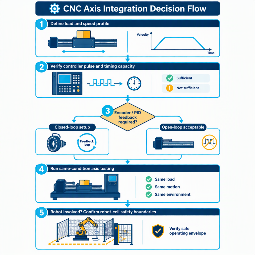
- Define the move: travel distance, target feedrate, acceleration, dwell time, reversal points and acceptable positioning behavior.
- Configure each candidate with its required step timing, position scale, velocity limit and acceleration limit.
- Check whether the controller can produce the required step frequency at the selected resolution and speed.
- If feedback is part of the candidate, log encoder, position or loop-related diagnostic data during the same move.
- Run the test long enough to observe heating, repeatability, fault response and recovery procedure under the duty cycle your machine will actually use.
- Use the same axis mechanics, supply voltage class, cable routing quality and load fixture when comparing options.
- Record lost-position symptoms, following behavior, alarm history, noise, vibration, thermal trend and recovery steps.
- For manual access during installation or inspection, switch off and disconnect machine power before opening cabinets, reaching into the axis area or touching wiring; then follow the machine and drive manuals for permitted access.
Add robot-integration and safety checks for automated cells
When the CNC motion system is part of a robot-loaded cell, motor selection must be coordinated with robot-cell safety requirements and risk assessment rather than treated as an isolated axis purchase.
A3 identifies ANSI/A3 R15.06-2025 as a revised American National Standard for industrial robots and robot systems safety requirements, with material addressing both industrial robots and robot applications or cells; confirm the adopted edition and any local requirements with the responsible safety authority or customer specification.
For automated loading, guarding and collaborative scenarios, review the relevant A3 robot safety standard documents before finalizing the drive, controller and emergency-stop architecture.
For the motion buyer, the practical point is simple: the selected motor-drive package must fit the cell’s stop strategy, interlocks, guarding concept, restart behavior and diagnostic expectations. A fast axis that is hard to integrate safely is not a complete solution.
Supplier-fit note for SZGH projects
For SZGH-related projects, use the servo-versus-stepper comparison as an engineering checklist, then confirm the exact controller, drive, motor and robot-control interfaces for the selected machine or retrofit scope.
SZGH presents product areas that include CNC machines, industrial robot arms, CNC plus robot integration, CNC controllers, servo drives, servo motors and robot controllers. Treat that as brand context, not as proof that every motor, feedback device or safety function fits every project.
For procurement, ask for the exact model documents, wiring diagrams, supported command interfaces, feedback options, tuning workflow, alarm list and integration responsibilities. That keeps the discussion useful without assuming unsupported specifications.
Conclusion
Choose the option that passes the same-condition speed, load, timing, feedback and safety checks on your machine, not the option that sounds stronger in a catalog comparison.
- If step pulse rate or timing is the limiting factor, solve the controller-interface issue before blaming the motor.
- If the job needs encoder feedback, loop diagnostics and controlled commissioning, include servo-style integration effort in the budget.
- If a robot is part of the cell, include robot-application safety requirements in the motion decision.
For most integrators, the best purchase process is a test plan: define the production move, run both candidates under the same conditions, compare total integration cost, then approve the package that meets the speed, load, feedback, tuning and safety requirements together.
FAQs about servo vs stepper motors for CNC
These questions help narrow the selection before you request model-specific motor and drive data.
Is a servo always better than a stepper for CNC?
No. A servo-style approach is easier to justify when feedback, loop control and diagnostics are required; a stepper-style path can still fit when the controller timing, load and accuracy requirements are within the tested limits.
What makes a stepper setup run out of speed?
The practical limit can come from the required pulse frequency after position scaling, because software step generation has a maximum rate that depends on the control computer and configuration.
What should I check first in a CNC retrofit?
Start with the required step timing, direction timing, position scale, velocity limit and acceleration limit, then compare those requirements with the controller and drive documentation.
When is feedback worth the added cost?
Feedback is worth considering when the axis needs encoder-based position information, loop-control behavior or diagnostic visibility during commissioning and fault recovery.
How should I compare cost without exact prices?
Compare cost categories: motor, drive, feedback device, controller hardware, cables, tuning time, diagnostic work and safety integration, then request itemized quotations for the actual axis.
Does robot loading change the motor decision?
Yes. Robot loading adds cell-level safety and risk-assessment considerations, so the drive and controller choice must fit the guarding, stop and restart strategy.
What documents should I request from the supplier?
Request exact model specifications, wiring diagrams, supported control interfaces, feedback options, tuning instructions, alarm descriptions and integration responsibilities for the selected CNC or robot project.


