


A robot welding fixture should be designed as one system for torch access, repeatable part location, reliable clamping, work-lead placement, visual clearance, spatter management and operator loading—not as a welded table with clamps added later.
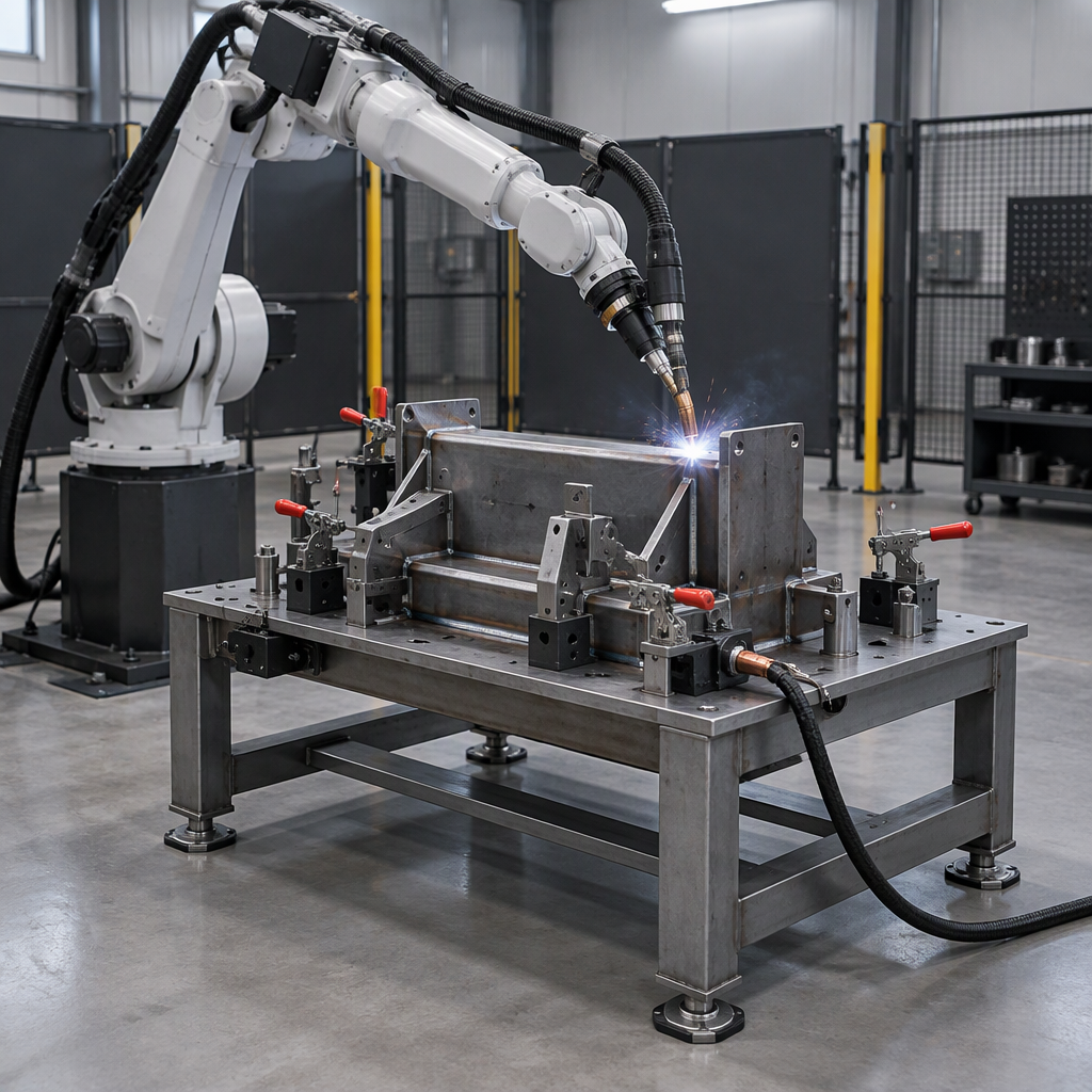
Start With Robot Access and Repeatability Together
The first fixture decision is not clamp type; it is whether the robot can reach every required weld while the part is located the same way at every load.
- Map the welds first. List seam positions, approach angles, gun clearance, visual clearance and any positions where the torch, nozzle, wire, fixture upright or clamp body could interfere.
- Define the loading condition. Decide how the operator or upstream equipment will place the part, remove the part and avoid disturbing locating points during loading.
- Keep access and repeatability linked. A locator that improves part control but blocks torch travel is not a complete solution; a wide-open fixture that lets the part shift is not repeatable.
- Review spatter exposure. Place critical locating faces, sensors and clamp mechanisms where spatter buildup is less likely to change part seating or obstruct movement.
Design Datums and Locators Before Adding Clamps
Choose the datums and fixed locators before selecting clamps, because clamps should hold the part against the reference system rather than create a different reference every cycle.
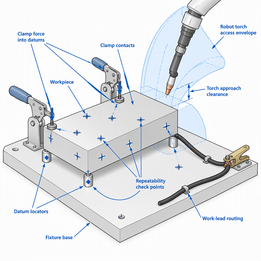
Fixture referencing is a robotics and manufacturing issue, not only a welding convenience: NIST describes tactile fixture research around referencing a sensor frame to a fixture frame and studying fixture contact surfaces for part referencing and calibration.
- Select stable reference faces. Use part features that can seat consistently against the fixture and can be inspected during trials.
- Make the robot path depend on the fixture, not operator judgment. The part should be forced into a known location before welding starts.
- Protect the datum surfaces. Keep the critical seating points cleanable and less exposed to weld spatter, slag or cable drag.
- Plan calibration checkpoints. Identify measurable features or check points that relate the part, fixture and robot coordinate system during commissioning.
Choose a Clamping Strategy That Does Not Block the Torch
A good clamping strategy restrains the part against the locators while leaving the robot torch, wire path, weld plume clearance and operator loading path unobstructed.
| Clamping choice | Use it when | Check before release |
|---|---|---|
| Low-profile mechanical clamps | The weld path passes close to the part edge and vertical clamp bodies would create torch interference. | Confirm the clamp handle, arm and fastener heads stay outside the robot approach and retreat paths. |
| Swing or toggle clamps | Operator loading needs open access and the clamp must move clear before part removal. | Confirm the open and closed positions do not enter the torch envelope or the operator’s safe loading area. |
| Pneumatic or sequenced clamps | The cell needs consistent clamping order, interlock feedback or integration with a robot sequence. | Confirm clamp status feedback, service routing and failure state before production trials. |
Plan Weld Circuit, Sensors and Services as Part of the Fixture
Treat work-lead placement, cable routing, sensing, air lines and service protection as fixture-design items, because they can affect arc stability, access, maintenance and repeatable loading.
- Place the work lead where current can return reliably without forcing the cable through the torch path or operator loading path.
- Separate weld cables, sensing leads and fixture services where practical so that movement, heat and spatter do not damage them.
- Provide protected routes for air lines, proximity sensors and clamp feedback cables if the fixture uses powered or monitored clamps.
- Leave visual access to important seating points so operators and technicians can see whether the part is fully located before the robot cycle begins.
- Keep spatter-prone zones away from precision locating faces, sensor targets and service fittings whenever the part geometry allows it.
Set Safety and Operator-Access Boundaries Early
Set the fixture boundary together with the robot cell boundary, because robot welding safety covers the robot system, welding process, ancillary equipment and human access around loading, maintenance and operation.
For safety-document planning, the American Welding Society catalog lists D16.1M/D16.1:2026, Specification for Robotic Arc Welding Safety, as covering safety requirements for the design, manufacture, maintenance and operation of arc welding robot systems and ancillary equipment; the same listing identifies the 2018 edition as historical. Confirm the edition and any local requirements for the destination market before relying on a safety file.
Prove Repeatability Before RFQ or Final Acceptance
Repeatability should be checked with repeated measurements under a defined method, not assumed from a fixture drawing or a single trial part.
- Choose the measured features. Pick weld-joint gaps, part datums, tack locations or inspection points that represent whether the robot will see the joint in the expected place.
- Repeat the loading cycle. Measure the same features across multiple load-and-clamp cycles rather than measuring one best-fit setup.
- Record the measurement method. State the gauge, operator method, check condition and whether the part was measured before or after welding.
- Use the results in the RFQ and acceptance plan. Convert the repeated checks into a practical fixture trial requirement instead of asking only for a general statement that the fixture is repeatable.
NIST’s Engineering Statistics Handbook explains analysis of repeatability using repeated measurements, repeatability standard deviations and pooling over appropriate runs, days or check standards to obtain a more reliable precision measure.
Prepare Integration Data for Control, Feedback and Commissioning
For a CNC-plus-robot integration project involving SZGH, prepare interface and commissioning data separately from fixture mechanics so the cell supplier can connect the fixture state, robot sequence and machine-side signals correctly.
- Identify which controller, robot controller, servo drive, servo motor or CNC machine interface must exchange signals with the fixture or welding sequence.
- List every fixture signal: clamp open, clamp closed, part present, part seated, station ready, fault, reset and any manual-mode permissive required for commissioning.
- Define which fixture positions must be visible during dry run, touch-up and weld-path teaching.
- Define commissioning checks that can be repeated and recorded, including part seating checks and repeated location measurements.
- Keep safety-related signals and access modes within the safety plan for the complete robot welding system.
RFQ Checklist for a Robot Welding Fixture
A useful RFQ should let the supplier judge access, part location, clamping, weld circuit, safety boundary, measurement method and integration requirements before quoting the fixture or robot cell.
- Part drawings, material information, weld locations and required joint presentation.
- Robot reach constraints, torch orientation limits, loading method and expected operator access points.
- Preferred datum scheme, critical locating faces and known part-variation issues.
- Clamping preferences, clamp sequence, service availability and required open/closed feedback.
- Work-lead location, cable routing constraints, sensor locations and spatter-prone areas.
- Repeatability check method, measured features, sample cycle plan and acceptance records.
- Controller, robot controller, CNC machine, servo and integration signals that the supplier must coordinate.
| If the project priority is… | Ask the supplier to confirm… |
|---|---|
| Maximum robot access | Torch approach, clamp clearance, cable movement and visual clearance at every weld. |
| Repeatable joint location | Repeated-load measurement method, measured features and acceptance data format. |
| CNC and robot integration | Signal list, controller interface, feedback devices and commissioning responsibilities. |
| Safety file readiness | Applicable robot welding safety standard edition, destination-market requirements and the cell-level access concept. |
Conclusion
Design the welding fixture around the robot’s real access path and the part’s repeatable reference system, then add clamps, services, safety boundaries and integration signals that support that system.
Before RFQ or acceptance, turn “repeatability” into measured checkpoints and repeated loading trials. That gives the integrator, fixture builder and robot application engineer a shared basis for design review instead of relying on assumptions.
FAQs About Robot Welding Fixture Design
Most fixture questions come back to four practical issues: can the robot reach the weld, can the part seat the same way, can the clamps hold without interference, and can the cell prove the result.
What is robot access in welding fixture design?
Robot access means the torch can approach, weld and leave every joint without colliding with clamps, locators, fixture posts, cables or the part itself. It also includes visual clearance and space for loading. Before manual maintenance access in the robot or fixture area, switch off and disconnect the applicable electrical power or battery source, and isolate any pneumatic, hydraulic or stored-energy source that can move tooling.
What makes a welding fixture repeatable?
A repeatable fixture locates the part against stable datums and clamps it consistently so the weld joint appears in the expected place from cycle to cycle.
Why design datums before clamps?
Datums define the reference relationship between the part and fixture. Clamps should push the part into that reference condition; they should not become the uncontrolled reference themselves.
Why does work-lead placement matter in the fixture?
Work-lead placement affects how the welding circuit is routed through the cell. It should be planned so cables do not obstruct torch motion, operator loading or protected fixture services.
Which safety standard should be checked for robotic arc welding?
The AWS catalog lists D16.1M/D16.1:2026 as the Specification for Robotic Arc Welding Safety and identifies the 2018 edition as historical. Confirm the applicable edition and destination-market requirements for the project.
How do you measure fixture repeatability before acceptance?
Use repeated loading and measurement cycles with a defined gauge, feature set and record format. A single successful setup does not show how consistently the fixture repeats.
What should be included in a robot welding fixture RFQ?
Include part drawings, weld locations, robot access constraints, datum strategy, clamp concept, work-lead routing, sensor needs, safety boundary assumptions, integration signals and repeatability-check expectations.


