


CNC tool changer integration should be treated as a verified sequence, not as a hardware add-on: define the tool command path, map control and feedback signals, reserve machine-cell space and utilities, assign responsibility boundaries, then prove each online state before releasing production.
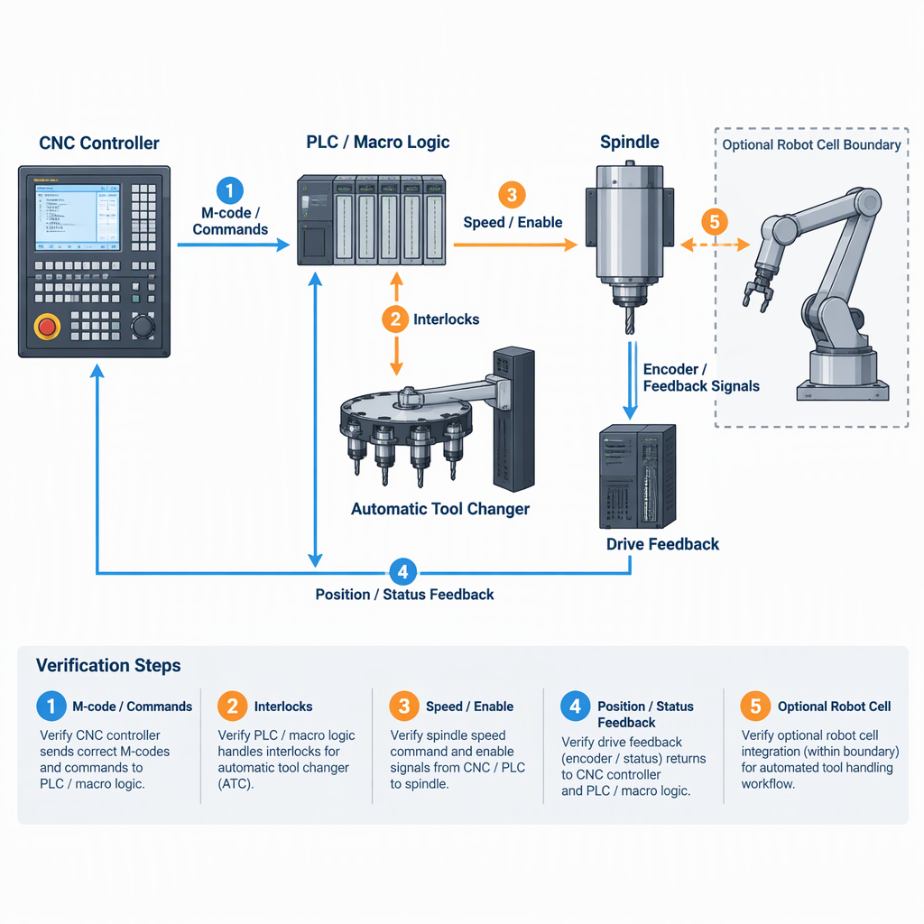
Define the integration scope before wiring
Start by separating the tool-change command, the control handshake, mechanical motion, drive feedback, optional robot handoff and acceptance checks, because CNC documentation commonly treats tool preparation and tool change acknowledgement as explicit interface events.
- Confirm how the control selects a tool before the change command. In one documented CNC environment, the M6 command changes to the most recently selected T word, so the selected tool and the physical tool-change action must be checked as separate assumptions.
- Identify whether the project will use built-in tool-change behavior, a remapped M6 flow, a macro, PLC logic or custom I/O interaction; LinuxCNC documentation describes tool-change remapping as a design choice involving iocontrol, prolog and epilog behavior.
- List the mechanical scope before cutting metal: magazine position, changer stroke, spindle orientation method, access door logic, chip and coolant exposure, service clearance, and the utilities required by the selected changer.
- Define upstream and downstream handoffs: CNC program command, PLC or macro sequence, servo or spindle status, robot-ready status where used, and the final tool-state update seen by the operator.
Build the M6 or tool-change sequence as a state path
Translate M6 into a state path with named preconditions and acknowledgements rather than a single instruction, because documented CNC behavior can stop the spindle, preserve the machine position and then call an adaptable tool-change subroutine.
- Record the state at command entry: selected tool, current spindle tool, spindle state, axis position and any movement the selected control permits during the tool-change routine.
- Define the program-level trigger: standard M6 behavior, remapped M6, or a macro/subroutine path. For open-control projects, LinuxCNC remap documentation shows why prolog, epilog and HAL interaction decisions belong in the design review.
- Create intermediate states for prepare, motion enable, clamp or unclamp, pocket index, spindle load, confirmation and fault exit, then assign a feedback point to each state.
- For any test that requires manual access to the changer, magazine, spindle or robot cell, switch off and disconnect the applicable power source before access, then follow the machine and tool changer manuals for permitted access points only.
Do not bypass guards, defeat interlocks or invent manual recovery motions during commissioning. If a state cannot be reached through the approved control path, stop the test and resolve the control, mechanical or safety-design issue before continuing.
Map the control interface, feedback and interlocks
The interface map should show every command output, feedback input and interlock that proves the changer has moved from one state to the next; LinuxCNC documentation describes tool-prepare/tool-prepared and tool-change/tool-changed handshakes as examples of this logic.
| Interface item | What to define | Verification focus |
|---|---|---|
| Tool preparation handshake | Signal path for requested preparation and prepared acknowledgement | Confirm that the CNC does not continue until the expected acknowledgement is present. |
| Tool-change handshake | Signal path for change request and change-complete acknowledgement | Confirm completion only after the mechanical and feedback states match. |
| Drive and spindle feedback | Required status such as stopped, oriented, clamped or ready, according to the selected machine design | Confirm that feedback is read before the changer enters a motion state. |
| Door, guard and cell interface | Permissive conditions for automatic motion and blocked conditions for access | Confirm that access and automatic motion cannot conflict. |
| Custom I/O for complex behavior | Digital or analog motion I/O where standard iocontrol behavior is not sufficient | Confirm signal scaling, polarity, timeout and fault response before production testing. |
- Use one signal name across the electrical drawing, PLC comments, macro variables and acceptance checklist.
- Record normal state, active state, timeout action and reset condition for every signal.
- Keep dry-run checks separate from spindle-loaded or robot-assisted checks.
Verify pocket, tool-number and indexing assumptions
Pocket and tool-number assumptions affect sequence verification because CNC tooling decisions include switching, loading and slot-centric indexing, so the integration test must prove that the requested tool, magazine pocket and actual spindle tool remain synchronized.
| Assumption | Risk if it is wrong | Buyer check |
|---|---|---|
| The T word represents the next selected tool | The control may execute M6 for a different selected tool than the integrator expects. | Run a non-cutting test showing selected tool, current spindle tool and final tool display. |
| The magazine slot or turret index matches the tool plan | A slot-centric indexing error can put the wrong tool at the exchange position. | Verify pocket map, empty-pocket handling and reload procedure. |
| Tool-length measurement happens inside or after the change flow | Offsets may be applied at the wrong time or not updated for the current spindle tool. | Check whether the tool-change subroutine also includes tool-length measurement logic in the selected control environment. |
Treat the magazine map as commissioning data, not only as operator setup information. If the sequence can continue with an unresolved tool number, empty pocket or failed index confirmation, the integration is not ready for production release.
Check controller, PLC and macro capability without overreading the datasheet
Evaluate the controller by asking whether it supports the specific sequence you need—ATC logic, PLC or macro customization and enough configurable I/O—rather than assuming that a general controller page proves a complete integration package.
- For a scoped example, the GH-1000MC-4 first-party product page presents a 4-axis CNC milling controller with ATC support, PLC and macro functions, configurable I/O and CNC plus robot integration navigation.
- Ask the supplier for the current controller manual, I/O assignment method, macro or PLC editing method, and supported tool-change examples for the exact model and software version being quoted.
- Check whether the available I/O count, voltage type, feedback type, variable access and alarm handling match the real changer, spindle, drive and cell design.
- Confirm who is allowed to edit the tool-change sequence after installation: the CNC supplier, machine builder, robot integrator, end user or a jointly approved commissioning engineer.
Use first-party controller pages as a starting point for capability screening, not as the final acceptance document. The buyer should request the current manual, wiring example and software-version notes for the selected controller before committing the interface design.
Set robot and cell-boundary rules conservatively
When a robot loads parts, handles tools or shares a cell with the tool changer, define the robot boundary as a separate integration layer; NIST describes robotics work areas such as manipulation, sensing, navigation, actuation and control, which are disciplines that can intersect with CNC automation.
| Boundary | Owner to assign | Commissioning check |
|---|---|---|
| Robot-to-CNC request | Robot integrator and CNC integrator | Confirm which system requests cycle start, tool change hold, door open, door closed and robot clear. |
| Shared cell access | Machine builder, robot integrator and end user | Confirm that automatic motion and manual access are separated by the approved safeguarding design. |
| Fault recovery | CNC supplier, robot integrator and end user | Define who can reset a partial tool-change or partial robot handoff, and what state must be proven before restart. |
| Safety validation | Qualified safety personnel for the project jurisdiction | Confirm applicable standards, local rules and risk assessment requirements with the responsible safety authority before release. |
Do not treat a robot-ready signal as proof that the cell is safe. It is only one integration state unless the project’s approved safety design defines it otherwise.
Verify the online sequence in staged tests
Verify the online sequence in stages: first prove command interpretation, then handshakes, then mechanical motion, then loaded tool state, and finally fault recovery, because remapped or macro-based tool changes depend on both control logic and acknowledgement behavior.
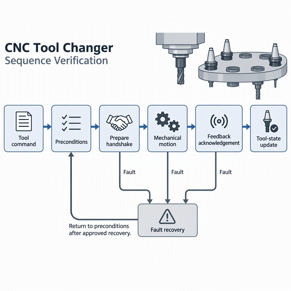
- Command-stage test: run a no-cutting program that selects a tool and calls M6, then verify selected tool, current spindle tool, spindle stop behavior and final displayed state.
- Handshake-stage test: force the sequence through preparation and change acknowledgements, checking that each state waits for the correct feedback and faults on timeout.
- Motion-stage test: with cutting disabled and safe access controlled, verify magazine index, arm or carousel motion, clamp/unclamp feedback and any spindle orientation requirement.
- Robot-stage test: if a robot participates, verify CNC hold, robot clear, cell permissive and recovery states before any automatic production cycle.
- Fault-stage test: simulate missing feedback, wrong pocket, incomplete clamp and emergency stop recovery according to the approved manuals and risk assessment.
- Before any manual access during testing, switch off and disconnect the relevant electrical, pneumatic, hydraulic or battery power source, then use only access methods permitted by the equipment manuals.
- Record the expected signal state before the test and the observed signal state after each transition.
- Do not release production until the same sequence works from automatic cycle, operator-initiated recovery and controlled restart.
Document responsibility boundaries for commissioning and support
A clear responsibility boundary prevents commissioning gaps: the party that defines a sequence state should also define its signal name, expected feedback, failure response and acceptance test.
| Work item | Typical accountable party to name | Document to request |
|---|---|---|
| M6 remap, macro or control behavior | CNC supplier or CNC retrofit engineer | Sequence description, editable logic location and software-version record |
| I/O handshake and HAL or PLC interaction | CNC integrator and electrical engineer | I/O map, signal polarity, timeout table and diagnostic screen list |
| Changer mechanism and utilities | Machine builder or tool changer supplier | Mechanical envelope, air or hydraulic requirements, lubrication and service access notes |
| Robot handoff | Robot application engineer | Robot-CNC interface list, safe positions, recovery method and cell-state table |
| Final acceptance | End user with all integration parties | Signed test record covering normal cycle, restart and defined fault cases |
- Put responsibility boundaries in the purchase specification before wiring starts.
- Require the same signal names in drawings, PLC or macro comments, robot logic and commissioning records.
- Keep support ownership visible for later software updates, tool magazine changes and robot program changes.
Conclusion
A reliable CNC tool changer project is commissioned as a controlled sequence: command, prepare, move, confirm, update tool state and recover safely.
- Map prepare and change handshakes before wiring the final panel.
- Prove selected tool, current tool and final spindle tool state during M6 testing.
- Use controller feature pages only as a starting point; request the exact current manual and I/O method for the selected model.
- Assign ownership for CNC logic, mechanical motion, utilities, robot handoff, safety validation and final acceptance.
FAQs about CNC tool changer integration
These questions help integrators turn the sequence plan into practical checks before commissioning.
What is included in CNC tool changer integration?
It includes the CNC command path, preparation and change handshakes, feedback inputs, macro or PLC logic, mechanical changer states, recovery behavior and any robot or cell boundary signals.
Is M6 always the whole tool-change sequence?
No. In documented CNC behavior, M6 can call a tool-change routine and may work with a previously selected T word, so the integrator still has to define the detailed machine actions and confirmations.
Which signals should be verified first?
Start with prepare request, prepared acknowledgement, change request, change-complete acknowledgement, spindle or drive ready feedback, and any fault or timeout state that blocks continuation.
Why does the pocket map matter?
Tooling decisions can depend on switching, loading and slot-centric indexing, so a pocket-map error can produce a correct-looking command with the wrong physical tool at the spindle.
Can a controller datasheet prove ATC compatibility?
A datasheet or product page can indicate ATC, PLC, macro or configurable I/O capability, but the buyer should request the current manual and model-specific wiring or logic method before treating it as compatible.
How should robot integration be handled?
Treat the robot as its own integration layer with defined manipulation, sensing, control and cell-state boundaries, then assign ownership for handoff, access control and recovery.
What proves the sequence is ready for production?
Readiness requires successful staged tests for command interpretation, acknowledgement behavior, mechanical motion, final tool-state update and defined fault recovery under the approved control path.


