


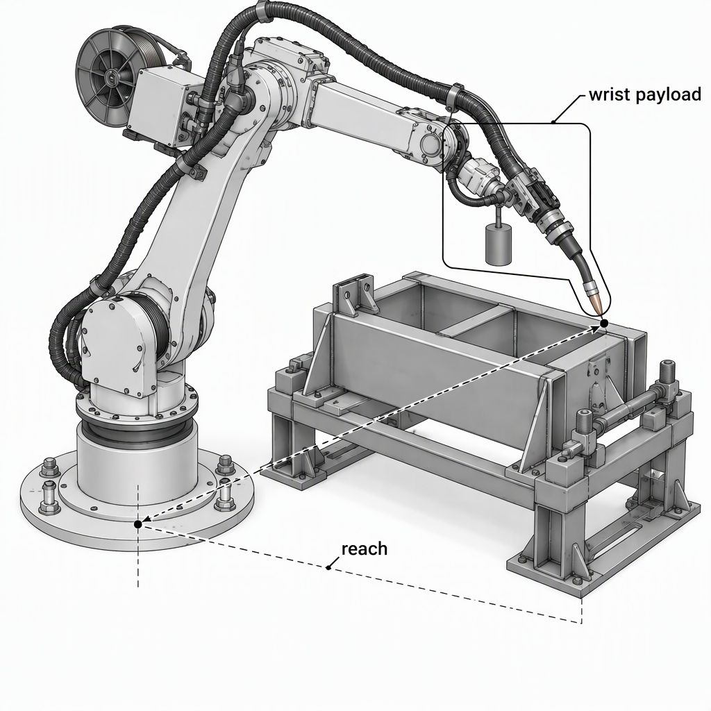
Two numbers choose the robot class for a welding cell: the total mass the wrist has to carry, and the greatest distance from the robot's mounting position to the furthest weld with the torch fitted. Work both out before you compare models, because payload and reach are published per model family and a wrong figure moves you into a different class. Guarding, risk assessment and operator training stay separate duties that selection does not settle.
How Do You Calculate the Payload a Welding Robot Must Carry?
Payload is the mass the arm has to carry and control at the wrist, not the weight of the part on its own. Add every item that travels with the arm, then leave a margin on the total: SZGH's published selection guidance budgets the part plus the end-of-arm tool with 20% on top, and that margin is what covers a heavier torch, a new fixture or a heavier part between jobs. SZGH manufactures CNC machines and industrial robot arms and develops its CNC controllers, servo drives, servo motors and robot controllers in house, and publishes that same rule of thumb for its own range.
| Line item | What to weigh | Why it changes the model class |
|---|---|---|
| Part or assembly | The heaviest part the cell will run, as it is presented to the robot | The usual starting number, and on its own it understates the wrist load |
| Torch and bracket | Torch body, neck and mounting bracket, including water-cooled lines | It sits furthest from the flange, so it adds the most lever load |
| Dress pack | Cables, wire conduit and air lines, routed as they will run on the arm | Mass and stiffness at the wrist affect how steadily the torch holds its angle |
| Arm-mounted feeder | Feeder unit, spool and the wire still on it | Adds kilograms that never appear in a part weight |
| Wrist devices | Collision sensor, breakaway coupling, seam tracker, adaptor plate | All of it hangs between flange and torch and counts in full |
| Margin | An allowance on the total, for example the 20% the published guidance suggests | A cell that later changes torch, fixture or part drifts toward the limit |
Which Torch and Cable Loads Do Buyers Usually Underestimate?
Everything that hangs at the wrist belongs in the payload figure, and the torch, its bracket and the dress pack are the items buyers most often leave out. Weigh them as they will be fitted in the cell, including the pull the cable bundle puts on the wrist when the arm is stretched to its furthest welding position.
- Torch body, neck and bracket, weighed assembled rather than taken from a catalogue mass.
- Torch cables and wire conduit, routed the way they will actually run on the arm.
- Air lines, plus water lines if the torch is water-cooled.
- Arm-mounted wire feeder, spool and the wire still on it.
- Collision protection, a breakaway coupling or a wrist adaptor plate.
- Seam-tracking sensor or camera, and any bracket it needs.
- Any second tool the arm carries, if one robot welds and handles parts in the same cycle.
- The heaviest part in the family the cell must run, not only today's job.
How Do You Measure the Reach a Welding Cell Really Needs?
Reach is the distance from the robot's mounting position to the point you must weld, measured with the torch fitted and held at the angle the joint needs. It is not the length of one arm section and it is not the length of the part. Published first-party guidance for this class of machine is to measure from the robot base to the farthest working point.
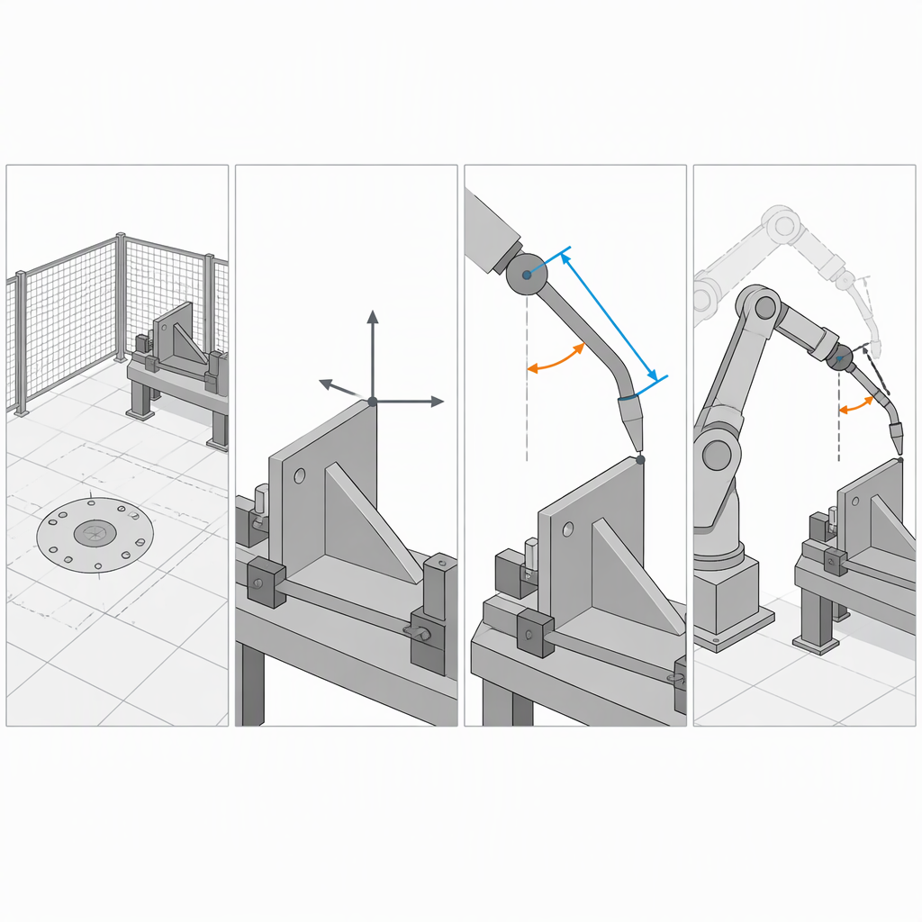
- Mark the proposed mounting position on the cell layout: floor, pedestal, wall, ceiling or gantry.
- Mark the furthest weld point in three dimensions, including tack positions and any reorientation the operator makes during the cycle.
- Add the torch, measuring from the wrist centre to the wire tip at the working angle for that joint.
- Check the wrist orientation available at that furthest point, so the torch can hold the angle instead of arriving at a posture the wrist cannot reach.
- Check the near limit too: a low weld, a deep inside corner or a sharp reorientation often demands more wrist articulation than the far edge does.
- Compare both limits with the supplier's working-envelope drawing and payload data for the model you are considering, and ask which mounting orientations those figures cover.
How Do Fixtures, Positioners and Table Height Change the Reach and Payload Decision?
Often they change it decisively: if the fixture or positioner turns the work toward the robot, the same welds arrive inside a smaller envelope and a smaller model can do the job. You pay for that in fixture repeatability, floor space, changeover time and the range of parts the fixture can hold, so compare the whole arrangement rather than the robot alone.
| Arrangement | Effect on reach demand | Effect on wrist payload demand | What it adds to the cell | Check before you commit |
|---|---|---|---|---|
| Fixed table, no positioner | Largest: the whole part must sit inside the envelope | Highest: the arm carries the torch to every joint | Little beyond the table and clamps | Whether every joint is reachable at the torch angle it needs |
| Single-axis rotator, turning only | Lower for welds around a part's circumference | Unchanged at the wrist | Rotator, drive and a repeatable locating fixture | Whether one rotation axis is enough for all joints |
| Two-axis positioner, turning and tilting | Largest reduction: welds can be presented one at a time | Unchanged at the wrist, but part mass moves onto the positioner | Positioner, controller interlock and floor space | Interlocking with the robot, and clamping access at every angle |
| Headstock and tailstock turning gear | Suits cylindrical work that can be rotated steadily | Unchanged at the wrist | Turning gear sized for the part | Part mass and length the turning gear can carry |
Where Does Robot Selection Stop and Cell Safety Begin?
Choosing the right reach and payload does not make the cell safe. Selection only establishes that the arm can carry the torch and reach the joints. Safety is a separate set of duties held by the employer who puts the cell to work: assessing machinery risks, applying guarding, keeping a safe system of work, and making sure only trained and competent people operate the equipment.
Machinery safety duties sit with the employer and the safe system of work, not with the robot specification. The HSE introduction to machinery safety explains that machinery risks must be assessed and managed, that safeguarding follows a hierarchy from fixed guards through interlocks to trip systems, and that suppliers must pass on residual risks for the user to manage.
Standard numbers belong in the cell specification. The International Federation of Robotics records that robot safety standards are prepared in ISO Technical Committee 299, Robotics, with ISO 10218-1, ISO 10218-2 and ISO/TS 15066 developed for industrial robotics and ISO 13482 for non-industrial robotics. Confirm the editions and national adoptions that apply in your market before writing them into a purchase contract.
What Should You Send With a Welding Robot Quotation Request?
Send the geometry and the load list, not just a part length: weld joint positions in three dimensions, the mounting position you intend to use, the payload ledger and the torch you plan to fit. Payload and reach figures only mean something against a stated mounting position and tool, which is why published guidance in this category measures reach from the robot base to the farthest working point.
- Part drawing with every weld joint marked, and each joint's position relative to the mounting surface.
- Proposed mounting position and orientation: floor, pedestal, wall, ceiling or gantry.
- A payload ledger: part, torch and bracket, cables and conduit, arm-mounted feeder, wrist devices, plus the margin you are applying.
- Torch model, or the torch angle and reach you need at the worst joint.
- Fixture or positioner arrangement, including whether the work turns during welding.
- The heaviest and the largest part the cell has to handle, if the part family varies.
- The envelope limits that matter most: the nearest weld, inside corners and any awkward reorientation.
- Local requirements your site must meet: guarding concept, operator access, and the standards your plant works to.
Conclusion
Size two quantities before you discuss models: a complete payload ledger with a margin, and a worst-case reach measured from the mounting position to the furthest weld with the torch fitted. Those two limits shortlist the model class; guarding, risk assessment and operator competence then have to be arranged separately for the cell you actually build.
- Payload is the part plus everything that travels with the wrist, plus margin.
- Reach is mounting position to furthest weld, with the torch at its working angle.
- A fixture or positioner can reduce both demands, at a cost in changeover time and floor space.
- Safety and operator competence remain the cell owner's duty, whatever model you choose.
Frequently Asked Questions
These are the questions that come up most often once the payload ledger and the reach check are on the table.
What should I check about a robot model's payload and reach data before comparing suppliers?
Check the conditions the figures are published under. Find out whether the payload is rated at the wrist flange, whether it changes with reach or with the load's centre of gravity, which mounting orientations the envelope drawing covers, and whether the tool is already included in the payload figure. Read repeatability and any arc-welding configuration from the same document. A headline payload number without those conditions cannot be compared with another model's number.
Should I compare payload first or reach first?
Start with the worst-case reach, because a robot that cannot put the torch on the joint has no useful payload for your cell. Shortlist the models that cover the furthest weld at the torch angle you need, then check each shortlisted model's payload at the reach you actually use, not at its maximum reach.
How much payload margin should I leave?
Published selection guidance for this class of machine suggests the part plus the end-of-arm tool with 20% on top, which is a reasonable starting point where you can weigh the torch and cables. Increase it if part weights vary between jobs, if the torch or fixture may be changed later, or if anything is mounted on the arm beyond the torch.
Do I need a six-axis robot for arc welding?
Payload and reach do not tell you whether the wrist can hold the torch at the angle a joint needs; that is an axis-count and wrist-range question. Where a weld needs one torch angle held throughout, check the wrist range of the model you are considering instead of inferring it from payload. Arc-welding models in the SZGH range are six-axis, including the HZ1500-B-6 arc welding robot.
Which standards and regulations apply to a welding robot cell?
Two layers apply. The International Federation of Robotics records that robot safety standards are prepared in ISO Technical Committee 299, Robotics, with ISO 10218-1, ISO 10218-2 and ISO/TS 15066 for industrial robotics. On top of those, your own national workplace rules set the employer's duties: risk assessment, guarding, safe systems of work and trained, competent operators, as the HSE describes for Great Britain. Confirm the adopted editions and any local amendments before you write them into a specification.
Can a positioner let me buy a smaller robot?
It can, when turning or tilting the work brings the joints into a smaller envelope. You pay for it in fixture repeatability, floor space and changeover time, and the fixture still has to locate the part accurately enough for the weld to be repeatable. Compare the whole arrangement, including the positioner's controller, against the cost of the larger robot.


