CNC retrofit axis
Focus on command type, feedback scaling, following-error limits, PID or feedforward terms, and whether the existing mechanics can support the requested motion profile.

Views: 0 Author: Site Editor Publish Time: 2027-01-02 Origin: Site


CNC servo drive tuning starts by confirming the command, feedback, error, output, PID and feedforward terms for the axis, then checking following error under the intended move profile before treating the result as acceptable.
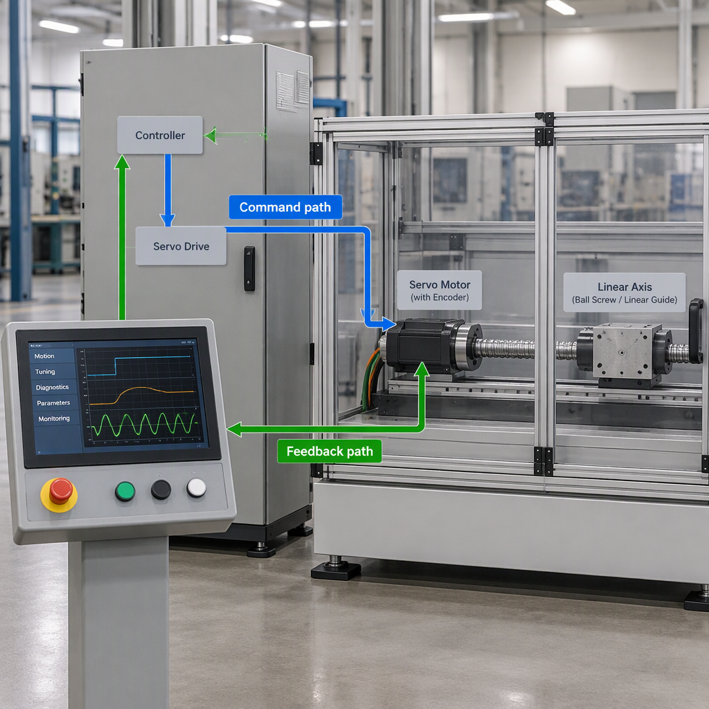
CNC servo drive tuning is the adjustment of a closed-loop control response so the measured axis motion follows the commanded motion with stable behavior and acceptable overshoot for the application.
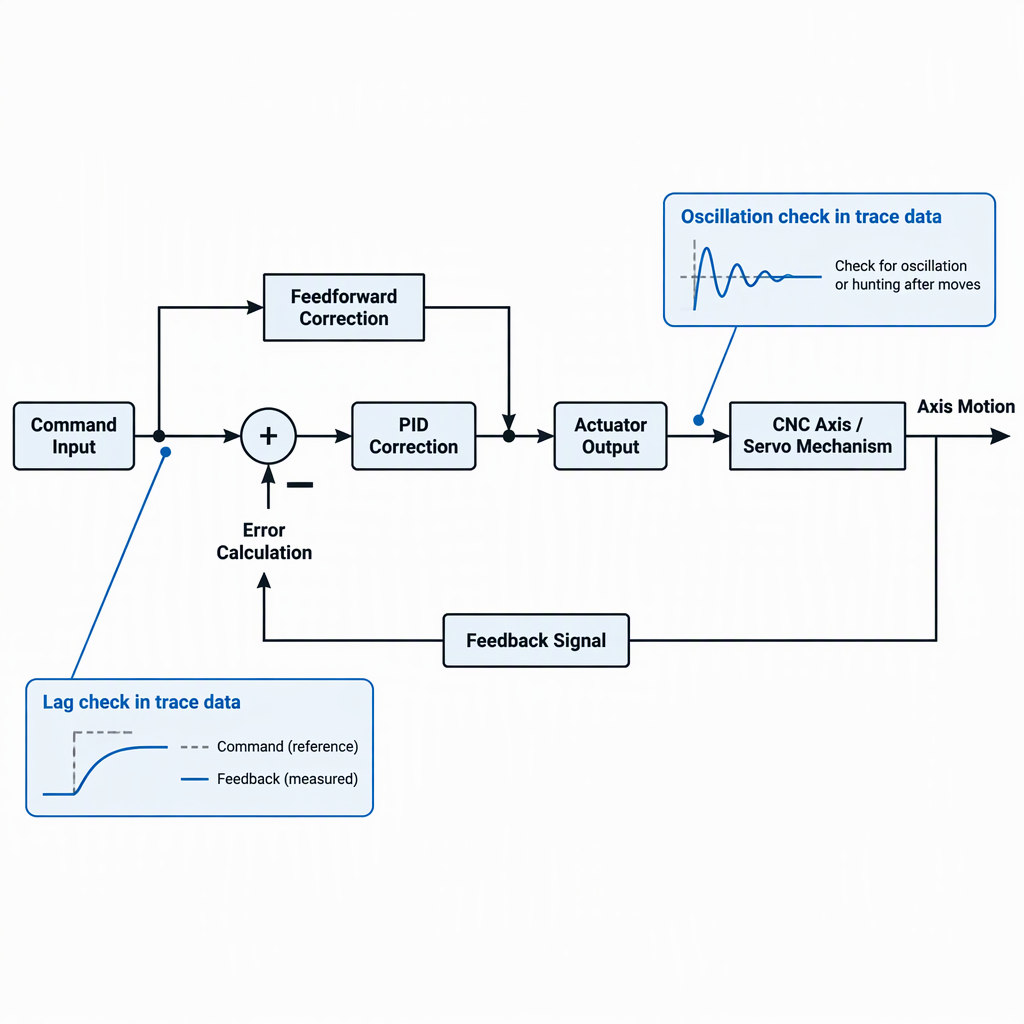
In a PID loop, the controller compares a measured value with a set point, calculates an error signal, and applies proportional, integral and derivative correction; LinuxCNC PID tuning documentation describes tuning as adjusting those parameters for the required response.
For a CNC axis discussion, the useful vocabulary is command, feedback, error and output: the command is the desired position or speed, feedback is the measured position or speed, error is command minus feedback, and output is the actuator command.
Before jogging an axis, forcing a test move or manually accessing a drive, cabinet, coupling, encoder or machine area, control hazardous energy so unexpected start-up or stored-energy release cannot injure personnel.
If a test requires opening a cabinet, touching wiring, moving a belt or ballscrew by hand, clearing a jam, or checking a feedback device physically, stop the tuning task, switch off and disconnect the relevant power source first, and use the machine’s approved manual-access procedure.
Collect the control interface, feedback source, axis units, command profile, feedback trace, error trace, limits and existing PID or feedforward terms before changing gains.
Tune one axis at a time, begin from a controlled baseline, make small parameter changes, and verify the response after each change instead of copying gain values from another machine.
There is no evidence-based universal PID gain value for every CNC servo drive; the correct response depends on the axis mechanics, motor, drive, load, feedback and application tolerance for overshoot.
An axis is suspect for oscillation when the measured response repeatedly hunts around the command instead of settling smoothly after a move or disturbance.
| Observation | What to check | Buyer decision |
|---|---|---|
| Feedback repeatedly crosses above and below the commanded value after stopping. | Check whether the loop is underdamped, whether proportional action is too aggressive, or whether integral action is winding the axis past the target. | Reduce risk before increasing gains; stable settling is more important than a fast but hunting response. |
| The axis vibrates at standstill or chatters during a small jog. | Check the trace at a low-risk move and compare the symptom with the command-feedback error. | Do not tune by sound alone; confirm the symptom in trace data before changing drive parameters. |
| Output command alternates sharply while the feedback does not follow proportionally. | Check output limits, feedback scaling and whether the actuator command is saturating. | Move from gain tuning to signal or drive diagnosis if the loop command is not producing proportional feedback. |
Lag is visible when feedback trails the command during the move, and following error is the command-minus-feedback difference that shows how far the axis is behind or ahead.
| Trace pattern | Likely meaning | Next check |
|---|---|---|
| Feedback follows the command shape but remains delayed during acceleration. | The axis may need feedforward review, acceleration-profile review or drive response review. | Compare error during acceleration, constant speed and deceleration before changing multiple parameters. |
| Error grows until the controller or drive reaches an output limit. | The command may be asking for more actuator output than the configured limit allows. | Check output limits and whether the move profile is realistic for the axis. |
| Feedback overshoots and then reverses repeatedly around the command. | The response may be too aggressive for stable settling. | Reduce the tendency to oscillate before increasing speed or acceleration. |
The practical diagnostic point is to inspect command, feedback, error and output together; looking at only the final part position can hide whether the servo axis lagged during the cut, transfer or robot-handshake move.
Stop changing gains when the trace suggests a mechanical, feedback, limit or safety problem rather than a simple loop-response issue.
| Stop condition | Why gain changes are risky | What to do instead |
|---|---|---|
| Command and feedback units or signs do not match. | A controller can calculate error only from the command and feedback it receives; wrong scaling can make gain changes misleading. | Correct the configuration and feedback direction before tuning. |
| The output is at its limit while the axis still lags. | More gain may only push the loop harder into saturation. | Review limits, load, acceleration demand and actuator sizing. |
| The axis oscillates immediately after a small gain increase. | The loop is already near an unstable response for the current mechanics and load. | Back away from the change and review damping, mechanics and feedback quality. |
| The check requires touching a moving component, opening a cabinet or clearing an obstruction. | Unexpected start-up or stored-energy release can occur during servicing and commissioning work. | Switch off and disconnect the relevant power source before manual access, then follow the approved hazardous-energy procedure. |
Do not bypass guards, defeat safety circuits or place personnel in the moving envelope to make a tuning trace easier to capture.
For retrofits and CNC plus robot cells, servo tuning planning should separate general control-loop checks from supplier-specific interface, feedback and integration details.
Focus on command type, feedback scaling, following-error limits, PID or feedforward terms, and whether the existing mechanics can support the requested motion profile.
Focus on safe commissioning boundaries as well as the axis response, because robot and machine motion can create unexpected start-up and stored-energy hazards during testing.
SZGH’s first-party site presents CNC machines, industrial robot arms, CNC plus robot integration, CNC controllers, servo drives, servo motors and robot controllers as offering areas, which makes interface and integration data relevant to an inquiry.
A useful tuning inquiry gives the supplier or integrator the axis data needed to understand command, feedback, error, output and limits before recommending parameter changes.
The practical rule is to tune from measured command, feedback, error and output data, prove that oscillation and following error are controlled under the intended move, and stop when the evidence points to mechanics, feedback, limits or safety rather than gains.
These questions help integrators decide whether to adjust parameters, collect more data or escalate the issue before commissioning a CNC axis or integrated cell.
No. PID tuning depends on the axis, mechanics, motor, drive, feedback, load and required response, so exact values should come from the drive documentation, machine builder or measured commissioning data.
No. Oscillation should be checked as a repeated control response around the command; mechanical looseness, resonance, feedback noise or saturation can also create vibration-like symptoms.
Following error is the difference between the command and feedback, so it shows how far the measured axis position or speed is from the requested value.
Feedforward should be reviewed when the command, feedback and error traces show repeatable lag during acceleration, constant speed or deceleration, rather than random or unsafe motion behavior.
Powered test moves require controlled commissioning conditions, but any manual access to cabinets, wiring, couplings, encoders, obstructions or moving machine areas requires switching off and disconnecting the applicable power source first.
The most useful information is the command interface, feedback source, scaling, existing gains, limits and traces that show command, feedback, error and output during the symptom.
Yes. A CNC plus robot cell adds coordinated-motion and commissioning boundaries, so the inquiry should include safe test conditions, the robot-machine handshake context and who is authorized to run powered moves.


2026-07-23 1156
SZGH-Technology-Full-Product-Catalog-Robots-CNC-Automation-2026.pdf
2026-06-18 46
SZGH CNC Milling Controller Catalog.pdf.pdf
2026-06-17 8
SCARA Robot White Paper.pdf
2026-06-11 30
SZGH-Collaborative-Robot-Cobot-Catalog-BCi-Series.pdf
2026-06-10 81
Shenzhen Guanhong Technology - Servo Motor Brochure 2025.4.pdf
2026-05-11 57
CNC MACHINE TOOL CATALOG.pdf


