


A CNC PLC input and output retrofit is planned as documentation before it is planned as wiring: inventory every device, classify each signal, justify the capacity you provision, separate safety functions into their own design, verify before production, and hand suppliers a scope that can be quoted.
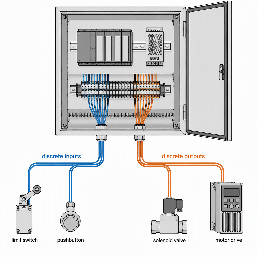
On a retrofit, the PLC inputs and outputs are the interface between the machine's physical devices and the control program. Inputs report machine state back to the control: limit and proximity switches, guard and door switches, pressure and level switches, drive ready and fault contacts, pushbuttons and selector switches. Outputs command the machine: contactor and relay coils, solenoid and hydraulic valves, drive enable and direction signals, indicator lamps, and lubrication or cooling devices. The IEC 61131 series is the reference structure behind that programming world: IEC 61131-3 defines Ladder Diagram, Function Block Diagram, Instruction List, Structured Text and Sequential Function Chart, and IEC 61131-9 extends the traditional digital input and digital output interfaces towards a point-to-point link.
On the control side, SZGH states that it develops the CNC controllers, servo drives, servo motors and robot controllers used in its own CNC machines and robot arms, and integrates both product lines into combined cells. Whether the existing control stays or is replaced, the planning sequence below is the same.
- Inventory the machine device by device before choosing any hardware.
- Classify every signal by function, domain and safety role.
- Size capacity and placement from the documented change list.
- Verify by inspection and record the result before production starts.
How do you inventory existing machine I/O before a retrofit?
Work device by device, not catalogue first. With the machine isolated, walk it against the existing electrical drawings and record every device that must communicate with the control: its function, its signal class, the control voltage actually present, the terminal or node it lands on, and whether it is retained, replaced or added. That list sizes the retrofit and is the document you hand to a supplier.
- Photograph and tag every junction box, terminal strip and drive before panel work, and keep the marked-up drawings.
- Record each device's role: safety function, interlock, sequence step, monitoring, operator command or indication.
- Note the signal class and the control voltage found on the machine, not the voltage you expect to find.
- Mark which devices already sit on a drive network, fieldbus or remote I/O node instead of discrete terminals.
- List what is missing: no PLC program backup, incomplete drawings, undocumented modifications by earlier owners.
- Establish the machine's support position: SZGH holds spare-parts inventory for its own machine models from 2010 onwards and supplies parts only for SZGH-branded equipment, so the spares route is defined for that base and must be established separately for any other make.
How should signals be classified before wiring is planned?
Classify by what each signal does and by what must happen when it fails, then record it that way on every drawing. The practical separation is discrete logic, analogue measurement, drive and feedback data, communication links and safety-related functions. Each class gets its own terminal groups, module type and test method, so a fault in one class cannot be hidden by another.
The IEC 61131 series reflects that separation: IEC 61131-9 extends the traditional digital input and digital output interfaces towards a point-to-point link, so a device reporting more than on and off is documented as a different interface, not an extra discrete point.
| Signal class | What it typically carries | What the plan must fix before wiring |
|---|---|---|
| Discrete input | Limit and proximity switches, guard and door switches, pushbuttons, selector switches | Terminal or node address, control voltage, safety role, and whether the device is retained or replaced |
| Discrete output | Contactor and relay coils, solenoid valves, indicator lamps | Output type, the device's current demand, and whether an interposing relay is required |
| Drive and feedback | Encoder, resolver or serial drive feedback, drive ready and fault contacts | Which drives stay, and which interface the new control supports for each one |
| Analogue process | Pressure, temperature, flow or load transmitters, proportional valve commands | Signal form, scaling and filtering, and where the analogue module physically sits |
| Communication | Fieldbus or Ethernet links to drives, remote I/O, robot or higher-level systems | Topology, master ownership, addressing and who commissions the link |
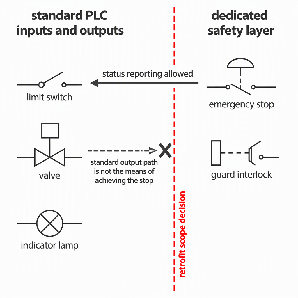
| Safety-related | Emergency stop, guard interlocks, safe stop of drives | Removal from the general I/O plan into a dedicated circuit with its own architecture |
How do you size I/O capacity and choose where the I/O sits?
Size the points from the device list plus the confirmed change list, then choose placement by distance, density and environment rather than preference. Cabinet-mounted I/O suits short runs and dense clusters; distributed I/O shortens cable runs but adds nodes, power and network dependence. There is no standard spare ratio: justify every spare point you add.
| Retrofit situation | Cabinet-mounted I/O | Field-distributed I/O |
|---|---|---|
| Devices concentrated in one or two panels | Fewer nodes, simple power distribution, easy to maintain | Adds nodes without shortening the runs that matter |
| Devices spread along a long machine | Long multi-core runs, more cable and terminations | Shorter runs and less cable, but more nodes to power and protect |
| Coolant, swarf and vibration exposure | The panel is protected, but long runs still pass through the hazard | Nodes must be rated for the environment or protected locally |
| Frequent mechanical reconfiguration | Every change becomes new cable and new terminals | Adding a node is quicker, but each change must be documented |
| Single failure must not stop the whole machine | Control is concentrated in one place | Segmentation is possible, but must be designed |
A network does not remove discrete points. SZGH's controller catalogue lists lathe and milling controllers with PLC ladder-diagram support and online PLC editing, including an EtherCAT milling controller with a stated 0.25 ms interpolation period, so drive and remote I/O traffic can share a fast link. The switches, valves, lamps and enable signals still need a physical point at the device.
Keep the data layer and the I/O layer separate when sizing: OPC UA exchanges information between systems; it does not replace device wiring or a safety circuit.
Budget the network as infrastructure: node power, cable routing, addressing discipline and node-dropout behaviour.
Where does safety sit relative to standard PLC inputs and outputs?
Emergency stop, guard interlocks and any function whose failure could injure someone belong in a separate safety design, not in the general-purpose I/O plan. The risk is assessed, an architecture that matches it is chosen, and the resulting circuit is verified on its own. Ordinary PLC I/O may report and display safety status; it must not be the means of achieving the stop.
Changing the safety functions can change the legal status of the machine. The European Commission states that Machinery Directive 2006/42/EC is the current EU machinery legislation, that Machinery Regulation (EU) 2023/1230 applies on a mandatory basis from 20 January 2027, and that the legislation applies where existing machinery is modified to such an extent that it becomes de facto new machinery. If the retrofit touches guards, interlocks or stop functions, treat the compliance route as open until the responsible person in your market confirms it, and agree the risk assessment and safety architecture before ordering any I/O.
Confirm the requirements where the machine will run; a cell accepted in one market may need extra measures in another.
The machine must be made safe before work starts on it. UK HSE guidance on maintenance of work equipment states that maintenance must be planned, that plant and equipment must be made safe before maintenance starts, and that this includes stopping moving plant, isolating electrical and other power supplies, locking off against reconnection and releasing stored energy such as compressed air or hydraulic pressure.
What must be verified at commissioning before first production?
Prove the retrofit in two passes: an isolated wiring check against the drawing set, then a functional check under power at the lowest speed that lets the machine move, with stop functions, guards and limits active. A retrofit that has only run in automatic mode has not been verified.
Where safety depends on how equipment was installed, inspection after installation and before first use is a specific duty. UK HSE guidance on PUWER regulation 6 states that such equipment should be inspected after installation and before first use, and after reassembly at a new site, with frequency set by risk assessment and results recorded and kept at least until the next inspection. Confirm the equivalent duty where the machine will run.
Isolate before opening anything. Switch the machine off, disconnect the relevant power source, lock off against reconnection, release stored energy such as compressed air and hydraulic pressure, and verify that the point you are about to work on is dead. Work only through the access the machine manual permits, and never defeat a guard or interlock to test a signal.
- Isolate and prove dead, then check the wiring against the drawings point by point and correct every drawing that disagrees with the machine.
- Power up with motion inhibited where the design allows, and confirm each input changes state when its device is actuated and each output drives only its own device.
- Test stop functions, guards and limits before any automatic sequence, so the machine can be stopped by design rather than by reaction.
- Run the sequence unloaded, then loaded, one function at a time, keeping a live list of deviations with point number and fix.
- Re-test the safety functions after any program or wiring change, because commissioning edits are the most common cause of a lost interlock.
- Record the outcome and file it where maintenance can find it.
- Every point on the I/O schedule is tested and signed, including points added during commissioning.
- Stop, guard and limit functions are proven with the machine able to move.
- Drawings, PLC program backup and parameter lists are updated to the as-commissioned state.
- Operators and technicians know which functions are safety functions and which are sequence functions.
What belongs in a CNC PLC I/O retrofit RFQ?
Send the scope, not a wish list: the device list with signal classes, the control boundary, what is retained and what is replaced, the safety functions in scope, the state of the machine documentation, the network plan and your acceptance criteria. That lets a supplier price modules, engineering, commissioning and documentation separately.
Include the programming interface you expect to keep. SZGH's controller catalogue lists lathe and milling controllers with PLC ladder-diagram support and online PLC editing, so ask which environment you will maintain after handover, who holds a backup of the program, and whether the tools and training are inside the quotation.
- Device list and I/O schedule: function, signal class, control voltage and retain, replace or add status for every point.
- Documentation status: drawings, PLC program backups and parameter lists, plus a note on anything missing.
- Control boundary: what the new control owns, what the existing control keeps, and how the two communicate.
- Drive and feedback detail: existing drive models and feedback types, and which drives stay.
- Safety scope: which guards, interlocks and stop functions the retrofit touches.
- Network plan: topology, master ownership, addressing and who commissions each link.
- Physical constraints: panel space, supply capacity, cable routes and the machine's working environment.
- Acceptance criteria: the tests you will run at commissioning and the documents you expect at handover.
Conclusion: what actually decides success in a retrofit I/O plan?
The list decides, not the parts. A documented device inventory, signals separated by class, capacity justified from the confirmed change list, safety designed as its own layer, and a commissioning record are what prove the retrofit works.
Start with the machine as it stands: what each device does, what it must report, and what has to change. Keep stop functions and interlocks in their own architecture.
Finish with verification: test point by point, prove the stop functions while the machine can still move, and keep the record.
Frequently asked questions about CNC PLC inputs and outputs
These questions most often stall a retrofit I/O plan: spare capacity, reuse, safety-driven changes, robot cells, networks and records.
How many spare I/O points should the plan include?
There is no defensible fixed percentage. Work from the confirmed change list: the points needed now, those needed by upgrades agreed in writing, and a small documented allowance per signal class for commissioning faults. Ask the supplier to price the spare allowance separately.
Does a retrofit that changes safety controls count as new machinery under EU rules?
It can. The European Commission states that the machinery legislation applies where existing machinery is modified to such an extent that it becomes de facto new machinery, that Machinery Directive 2006/42/EC is the current EU legislation, and that Machinery Regulation (EU) 2023/1230 applies on a mandatory basis from 20 January 2027. Changing guards, interlocks or stop functions is exactly the kind of modification that raises the question, so confirm the compliance route with the responsible person in your market before ordering.
Can the original machine's existing PLC and I/O be reused?
Sometimes, and the decision should follow the device list rather than the age of the panel. Reuse works when the existing control still has supported programming tools, a program backup, a documented spare point or module for the confirmed changes, and no safety function that must move to a different architecture.
Does a fieldbus or OPC UA layer replace hard-wired I/O in a retrofit?
No, they answer different questions. The OPC Foundation defines OPC UA as a platform-independent, service-oriented architecture with client-server and publish-subscribe access, which makes it a route for exchanging information between systems. SZGH's controller catalogue likewise lists an EtherCAT milling controller with a stated 0.25 ms interpolation period. Switches, valves, lamps and enable signals still land on physical points, and stop functions still need their own architecture.
How do I plan I/O for a robot cell added beside an existing CNC machine?
Treat the interface between the two controls as a designed interface, not an afterthought: agree which side owns each interlock, which signals pass between them, and how a stop on either side stops both. SZGH states that it develops its own CNC controllers, servo drives, servo motors and robot controllers and integrates CNC machines and robot arms into combined cells, which is one route to a documented handshake between the two controls.
SZGH also states that its robot arms run on a motion controller it develops itself, and that its CNC machines and robot arms carry CE certification with certificate number EBO2307022-V060 available on request. Ask any supplier for the certificate reference that applies to the equipment actually being supplied, rather than relying on a category statement.
What records should be kept after the retrofit?
Keep the as-commissioned drawings, the I/O schedule with the test result for every point, the PLC program and parameter backup, the risk assessment and safety architecture documents, and the inspection record. File them with the machine, not the project.
How do I keep the new I/O plan maintainable?
Use one tag for each point everywhere it appears: drawing, terminal, PLC symbol, HMI and I/O schedule. Record what each point is for as well as where it is wired, mark which points are safety functions, and use the same naming convention in the RFQ.


