


A closed-loop stepper motor makes sense on a CNC axis when you want stepper-style command simplicity with encoder-based feedback for position mismatch or stall handling, but it should be screened against the axis load, mechanics, controller interface, tuning needs, and whether the job really calls for a servo-class motion system. Industrial drive choices also need checks around feedback sensing, communication, EMC immunity, and safety-related design context.
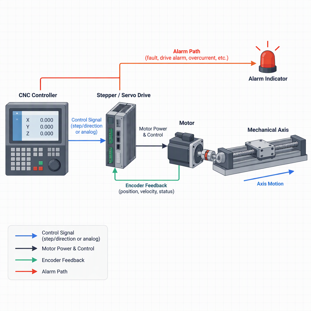
What a closed-loop stepper changes on a CNC axis
A closed-loop stepper adds feedback to the stepper drive system so the drive can compare commanded motion with actual motor movement and react to a stall or position mismatch.
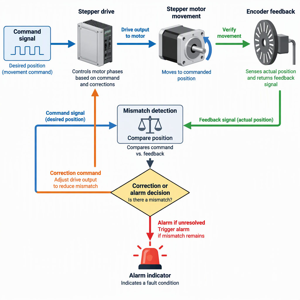
Texas Instruments describes a reference design for closed-loop stepper stall detection that uses an optical rotary incremental encoder with a DRV8880 stepper driver, which illustrates the basic architecture: command, drive, motor, feedback, and a detection decision.
Analog Devices describes closed-loop stepper control as feedback-based adjustment of current values or Step/Dir outputs, and distinguishes that approach from classical field-oriented control.
For a CNC integrator, the practical change is not simply “more accuracy.” It is the addition of a feedback loop that must be matched to the mechanical axis, encoder location, controller command format, drive configuration, and fault-response strategy.
When a closed-loop stepper makes sense
A closed-loop stepper is worth shortlisting when the axis benefits from feedback-based stall or mismatch detection but the application can still fit within a stepper-drive architecture.
| Axis condition | Why it points toward a closed-loop stepper | Buyer check before selection |
|---|---|---|
| Missed steps or stall risk would create scrap or interruption. | Encoder feedback can support stall or mismatch detection in a closed-loop stepper implementation. | Define how the controller should react: stop, alarm, retry, or hand off to a machine-level fault routine. |
| The machine already uses pulse-style Step/Dir command concepts. | Some closed-loop stepper controllers can work with Step/Dir-related control approaches while using feedback for regulation. | Confirm signal voltage, pulse rate, direction logic, enable, alarm, and controller compatibility. |
| The encoder can be mounted directly on the motor axis. | Direct motor-axis feedback reduces coupling complications that can occur when feedback is taken through belts or other transmission elements. | Check whether the feedback measures the motor shaft, the load, or a transmission element between them. |
| The axis is part of a wider industrial motion system. | Drive-system design commonly includes feedback sensing, communication, EMC, and safety-related context, not only the motor body. | Review cabinet wiring, grounding, communication, fault handling, and machine integration before ordering. |
A closed-loop stepper should not be treated as a universal fix for backlash, weak mechanics, poor tuning, or unsuitable feedback placement. If the encoder does not represent the motion that matters to the process, the loop may not solve the buyer’s real positioning problem.
Closed-loop stepper vs open-loop stepper vs servo
Choose among open-loop stepper, closed-loop stepper, and servo by matching the axis requirement to feedback, control bandwidth, communication, torque-speed behavior, and fault-response expectations.
| Option | Best fit | Main integration questions | When to reconsider |
|---|---|---|---|
| Open-loop stepper | Simple axes where the load is predictable and the process can tolerate operation without encoder-based mismatch detection. | Can the axis run without feedback-based confirmation, and are stall margins adequate? | Reconsider when stall or position mismatch needs to be detected by the drive system. |
| Closed-loop stepper | Axes that need stepper-style control with feedback for stall or mismatch handling. | Can the encoder be placed appropriately, and can the controller accept the drive’s command and alarm interface? | Reconsider if belt coupling, load-side compliance, or tuning requirements make a simple motor-shaft loop insufficient. |
| Servo | Motion systems where position, speed, torque control, feedback sensing, and industrial communication requirements are central to the design. | What feedback device, drive communication, EMC environment, and safety-related architecture are required? | Reconsider if the axis requirement is simpler than the servo system being specified and the added integration burden is not justified. |
A servo is not automatically “better” for every CNC retrofit, and a closed-loop stepper is not automatically “enough.” The selection should follow the axis duty, mechanics, controller ecosystem, and fault-handling requirement.
Integration checks before you specify the drive
Before specifying the drive, confirm the command interface, feedback device, alarm path, electrical environment, and machine-level response to faults.
- Command format: confirm whether the CNC controller and drive will use Step/Dir, another pulse method, SPI-related configuration, or a higher-level industrial communication approach.
- Encoder position: confirm whether the encoder is on the motor axis or affected by belts, couplings, screws, gearboxes, or load-side compliance.
- Mismatch response: define what the drive and CNC control should do when feedback indicates a stall or position mismatch.
- Industrial environment: review EMC immunity, grounding, cable routing, communication robustness, and feedback-sensing reliability in the actual machine cabinet.
- Drive-system scope: confirm whether the axis needs position control only, or also speed, torque, communication, and safety-related integration features.
TI’s servo and stepper drives overview groups motor-drive design around control, feedback, industrial communication, EMC immunity, and functional-safety-related design areas, which is a useful checklist frame for integrators.
If an inspection requires opening a CNC cabinet, drive enclosure, terminal cover, or robot-axis electrical area, switch off and disconnect the relevant mains power or battery source before manual access, then follow the machine and drive manuals for permitted access only.
Limits, tuning, and safety boundaries
Do not blame or credit the motor alone: closed-loop stepper results depend on feedback placement, mechanics, controller configuration, tuning, and how the machine handles faults.
Analog Devices notes in its TMC4361A closed-loop motor-control application note that encoder placement directly on the motor axis can avoid unwanted coupling effects, while belt or non-direct feedback arrangements may require PID regulation.
- Check whether feedback represents the motor shaft, the driven screw, the gantry, or the actual cutting or handling point.
- Check for mechanical backlash, loose couplings, belt elasticity, resonance, binding, lubrication issues, and axis imbalance before changing the motor type.
- Ask how tuning parameters are set, stored, locked, and documented for repeatable machine commissioning.
- Check whether the drive interface fits the machine’s communication, EMC, feedback, and safety-related design constraints.
- Do not compare motors only by holding torque; review the required speed range, acceleration, duty cycle, load inertia, and acceptable following-error behavior with the supplier.
A closed-loop stepper can improve fault awareness in the drive system, but it cannot remove the need to engineer the mechanical axis and tune the motion loop around the real load.
Safety boundary for CNC and robot integration
Closed-loop motor feedback should be treated as a motion-control feature unless the machine’s safety architecture separately validates it as part of a safety-related control function.
Industrial drive design can include functional-safety-related motor-drive areas, but a normal encoder feedback loop for stepper control is not, by itself, proof of a safety function for a CNC machine or robot cell.
For CNC retrofits and robot integration, define emergency stop behavior, guard interlocks, safe stop requirements, restart prevention, drive-enable logic, and fault reset procedures at the machine-system level. Ask the supplier and the machine builder which safety functions are included, which are excluded, and which documents apply to the final integrated machine.
Before manual clearing, adjustment, wiring checks, or access near moving axes, switch off and disconnect the relevant power source and follow the machine manual’s lockout and permitted-access procedure. Do not rely on a closed-loop alarm as a substitute for energy isolation.
Data to confirm before requesting a quote
A useful RFQ should describe the axis, motion requirement, feedback expectation, controller interface, electrical environment, and safety boundary before asking for a motor recommendation.
- Machine type, axis name, travel length, screw or belt type, gear ratio, and mounting envelope.
- Moving mass, load inertia, cutting or handling force, vertical-axis counterbalance condition, and expected duty cycle.
- Required speed, acceleration, positioning repeatability target, homing method, and acceptable fault response.
- Controller command interface, including Step/Dir requirements or other control and configuration methods.
- Feedback requirement, including whether stall detection, position mismatch detection, or alarm output is required.
- Encoder location and whether feedback is taken directly from the motor axis or through a transmission element.
- Cabinet voltage, grounding, cable length, EMC environment, communication needs, and safety-related integration expectations.
- Any retrofit constraints: existing controller, available I/O, mechanical adapter limits, enclosure space, cooling, and documentation requirements.
Send this information before requesting a recommendation. It helps the supplier compare a closed-loop stepper, open-loop stepper, and servo option without assuming performance numbers that only a machine-level test can confirm.
Conclusion
A closed-loop stepper makes the most sense when feedback-based stepper control matches the CNC axis requirement, the encoder placement is appropriate, and the machine does not require a servo-oriented architecture.
- Use closed-loop stepper feedback where stall or position mismatch detection matters.
- Check encoder location and tuning boundaries before treating the option as a simple drop-in replacement.
- Compare the full drive system, including communication, EMC, feedback, and safety-related integration context.
The best selection rule is practical: start from the axis duty and fault-response requirement, then choose the simplest motion architecture that can meet it with documented interfaces, safe integration, and a credible commissioning plan.
FAQ
These questions help CNC integrators and retrofit teams screen the application before choosing a motor and drive package.
Will a closed-loop stepper automatically improve CNC accuracy?
No. Feedback can support closed-loop control, but final axis accuracy depends on mechanics, feedback placement, tuning, controller behavior, and the load path.
When should I choose a servo instead?
Consider a servo when the axis requirement centers on broader position, speed, torque control, industrial communication, feedback sensing, and system-level drive integration.
When is an open-loop stepper still reasonable?
It can be reasonable for a predictable, low-risk axis where the process can tolerate operation without encoder-based mismatch detection and the mechanical margins are well understood.
Why does encoder location matter?
Encoder location determines what motion the loop actually sees. Direct motor-axis feedback avoids some coupling effects, while belt or non-direct arrangements may need additional regulation.
Can I keep my existing CNC controller?
Possibly, but you must confirm the drive’s accepted command interface, configuration method, enable and alarm signals, and how the CNC control will respond to a feedback-related fault.
Is closed-loop feedback a machine safety function?
Treat it as motion-control feedback unless the complete machine safety architecture separately defines and validates it as part of a safety-related function.
What should I send with an RFQ?
Send the axis mechanics, load, travel, speed, acceleration, controller interface, encoder expectation, cabinet environment, fault-response requirement, and any safety or retrofit constraints.


