


Treat robot-to-CNC connection as cell integration: confirm the cell boundary, utilities and interface, then verify the handshake through manual, dry-run and automatic tests.
Pre-integration checks before wiring the robot to the CNC
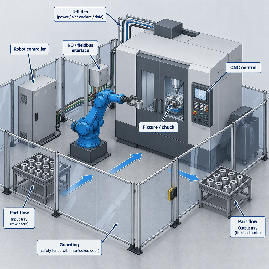
Before wiring, confirm the CNC, robot, tooling, workholding, guarding and utilities work as one cell.
- Confirm the CNC model, controller generation, available robot interface option, electrical drawings and permitted external-cycle functions.
- Map the physical flow: raw part location, robot reach, tool path clearance, door or access opening, chip and coolant exposure, finished-part exit and reject handling.
- Check utilities before layout freeze: power, air, workholding, coolant, chip removal and network cabinet space.
- Assign ownership for CNC changes, robot program, gripper, fixture feedback, guarding, risk assessment, acceptance and maintenance documents.
- Before manual wiring, inspection or cell access, switch off and disconnect applicable electrical, pneumatic and hydraulic energy using the site lockout procedure and machine-builder manuals.
Choose the interface layer and define the boundary
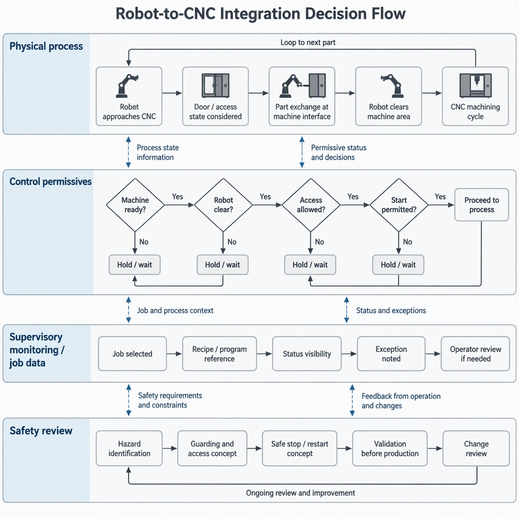
Use control interfaces for permissives and cycle exchange, and data interfaces for status; monitoring must not replace a documented handshake.
| Layer | Typical role in CNC robot integration | Buyer decision |
|---|---|---|
| Discrete I/O or safety-rated I/O where specified | Exchange ready, request, permission, cycle state, clamp state, door state, alarm and reset categories using documented controller functions. | Use when the machine builder provides approved signal points and the cell needs deterministic permissive logic. |
| Fieldbus or industrial Ethernet | Carry control and status bits between controllers through a configured network interface. | Use when both controllers support the same network and the project can document ownership of addressing, diagnostics and recovery. |
| Supervisory data interface | The OPC UA for Machine Tools Part 1 scope covers machine monitoring and job-management information for higher-level systems such as MES, SCADA, ERP and analytics. | Use for visibility and job context, while keeping the motion handshake and safety functions separately validated. |
OPC UA for Machine Tools can expose machine status or job overview data to supervisory systems, but it does not prove robot entry permission, chuck state, part-present feedback or automatic cycle recovery.
Set safety and responsibility boundaries before automatic motion
Treat the robot, CNC, workholding and guarding as one hazardous cell, and agree on the safety boundary before automatic motion.
NIOSH describes workplace robot systems as capable of struck-by, caught-between, crushing or trapping, slip, trip, fall and electrical hazards, so safety professionals must prevent added worker risk.
- Define safeguarded space, access points, teach positions, maintenance positions and expected human tasks.
- Confirm that guards, interlocks, emergency stops and enabling devices are evaluated by qualified safety personnel for the specific cell.
- Do not bypass guards or defeat interlocks to make a handshake test pass.
- Require safe-state behavior for loss of air, loss of part grip, CNC alarm, robot fault, network loss and emergency stop.
- Document who may reset the cell, what must be inspected before reset and which alarms require engineering review.
For general robotics hazard context, see the CDC/NIOSH overview of robotics in the workplace; then apply current robot, CNC and local requirements for the installation.
Connect the robot, CNC and peripherals in a staged workflow
Commission in stages: mechanical fit, utilities, control wiring, signal mapping, manual tests, dry runs and guarded automatic cycling.
- Freeze the cell layout after checking reach, door opening, fixture access, gripper clearance, cable routing and escape paths.
- Install end-of-arm tooling, part-present sensing and any fixture or chuck feedback according to the approved mechanical and electrical documents.
- With power and stored energy isolated before manual access, connect the documented I/O, fieldbus or interface module; label both controller-side and field-side terminations.
- Configure robot and CNC I/O comments and diagnostics so each signal category can be observed.
- Test each peripheral alone: gripper open/close, fixture clamp/unclamp, door or access function where permitted, part-present sensor and reject path.
- Run the robot path at safe commissioning speed under qualified supervision before allowing the robot to request a CNC cycle.
Verify the robot-CNC handshake before production
A handshake is verified when each request, permission, action, completion and fault-recovery condition works in order under safe test conditions.
- Start with manual single-signal tests: force no motion and confirm each controller sees the correct input and output state.
- Test permissives with the CNC idle: robot at safe position, fixture state known, part-present state known and no active alarm.
- Test the load sequence without cutting: request access, open or enable access as documented, load part, confirm clamp or fixture feedback and withdraw robot.
- Test cycle permission: robot clear, CNC ready, cycle request valid, cycle active observed and cycle complete returned.
- Test abnormal cases: missing part, unclamped part, robot not clear, CNC alarm, emergency stop, lost air and reset attempt.
- Release automatic production only after the team signs off signal order, safe-state behavior, operator instructions and recovery limits.
- Record the controller screen, electrical drawing reference and expected state for every signal category.
- Verify both directions of communication; a bit that turns on is not enough if the receiving controller does not act correctly.
- Keep the first production trial separated from the engineering dry run, with supervision and defined stop criteria.
Build a handshake signal checklist for commissioning
Use signal categories, not guessed names, because CNC M-codes, macro variables and robot I/O depend on the controller and machine-builder implementation.
| Signal category | What it should prove | Commissioning check |
|---|---|---|
| CNC ready | The machine is in a condition where an external automation request may be considered. | Confirm the state changes correctly after reset, alarm and mode changes. |
| Robot clear | The robot and tooling are outside the machining envelope or in the documented safe position. | Check the robot program position, not only a cabinet output. |
| Access or door permission | The cell may perform the documented load or unload action. | Confirm the machine builder permits the function and that guarding remains effective. |
| Clamp or fixture confirmed | The part is held before machining starts. | Test both true and false states, including air or hydraulic pressure loss where applicable. |
| Cycle active and cycle complete | The CNC has accepted the request, run the intended cycle and reached the documented completion condition. | Compare controller state, program end condition and robot wait logic. |
| Alarm, fault and reset | Both controllers enter a safe recoverable state or a locked engineering-review state. | Prove that reset cannot restart motion unexpectedly. |
- Use the machine builder’s exact signal names in the final commissioning document.
- Separate production logic from diagnostic bits so operators do not depend on hidden engineering screens.
- Require a tested response for every signal stuck on, stuck off or changing in the wrong order.
Keep monitoring data separate from validated control
Monitoring data can help supervisors see machine state, but robot entry permission, cycle start, clamping and fault recovery still need a validated control path.
Do not use a dashboard value, report tag or production-status screen as the sole permissive for robot motion unless the CNC builder, robot supplier and safety review explicitly approve that architecture.
The OPC UA for Machine Tools Part 1 page identifies machine monitoring and job management as its stated companion-specification scope, which supports separating supervisory visibility from the robot-CNC handshake that directly permits motion.
If a project also needs MTConnect data, ask for the current official specification, the machine builder’s supported implementation and the integrator’s responsibility matrix before assigning any production-control role to that data path.
Handover acceptance checks for CNC robot integration
Handover should prove the cell works, stops safely, recovers predictably and can be maintained from documented instructions.
- Approved layout, electrical drawings, network map, I/O list, robot program backup and CNC option or parameter record.
- Signed handshake test sheet covering normal load, normal unload, cycle complete, alarms, emergency stop, reset and power recovery.
- Safety review records addressing robot-cell hazards such as impact, trapping, electrical exposure and slips or trips around the cell.
- Operator instructions for start-up, stop, part change, reject handling and when to call maintenance or engineering.
- Maintenance instructions that require energy isolation before manual access to the robot, CNC enclosure, gripper, fixture or guarded space.
| Acceptance area | Pass condition | Who should own it |
|---|---|---|
| Control handshake | Every normal and fault sequence has been demonstrated and recorded. | Controls integrator with CNC and robot support as required. |
| Safety functions | Access, stop, reset and recovery behavior match the project risk assessment. | Qualified safety owner and end user. |
| Production readiness | Parts can be loaded, machined, unloaded and rejected according to the agreed process. | Manufacturing engineering and operations. |
| Documentation | Operators and maintenance staff have usable instructions and current backups. | End user with integrator handover support. |
Conclusion
The right CNC robot integration decision is to define the cell boundary first, then connect only documented interfaces, verify the handshake in stages and keep monitoring, control and safety roles distinct.
A reliable robot-to-CNC connection comes from disciplined integration: confirm the machine-builder interface, isolate energy before manual access, validate each permissive and fault case, and hand over drawings, backups and recovery rules the production team can use.
FAQs about CNC robot integration and handshake verification
Most integration questions come down to interface choice, safety responsibility, signal proof and what must be documented before production.
Can any CNC machine be connected to a robot?
Not automatically. The CNC needs a documented way to exchange permissives, cycle status and fault information, and the mechanical cell must also allow safe robot reach, part handling and maintenance access.
Which interface is best for CNC robot integration?
The best interface is the one the CNC builder and robot supplier document for the required control task. Discrete I/O, fieldbus and supervisory data can all have roles, but they are not interchangeable.
Can OPC UA replace the robot-CNC handshake?
OPC UA for Machine Tools Part 1 supports machine monitoring and job-management information for higher-level systems, so use it for visibility unless the machine builder specifically documents a control role for the project.
Which M-code should start the robot cycle?
Use the code, macro or ladder function specified by the CNC builder for that machine and option package. Do not copy a code from another brand, controller generation or retrofit without confirmation.
What should be tested before automatic production?
Test normal loading, unloading, cycle start, cycle complete, missing part, unclamped part, robot not clear, CNC alarm, emergency stop, reset and power recovery before releasing the cell.
Who owns safety in a robot-tended CNC cell?
Safety ownership must be assigned for the complete cell because robot systems can introduce impact, trapping, electrical and slip or trip hazards; the end user, integrator and suppliers should document their responsibilities.
Is monitoring data enough for commissioning?
No. Monitoring data helps engineers see status and diagnose production flow, but commissioning still needs direct proof that the control handshake and safe-state behavior work under normal and abnormal conditions.


