


Connecting a spindle to a CNC controller is a multi-signal project, not a cable choice. Before the first powered run, confirm the signal groups that cross the boundary — speed command, enable and fault chain, spindle feedback, at-speed and zero-speed status, and orient where the spindle is positioned. Then confirm panel space, supply and cooling from the documentation of the exact drive frame, agree who owns safety and conformity on the modified machine, and prove the link with a staged first run.
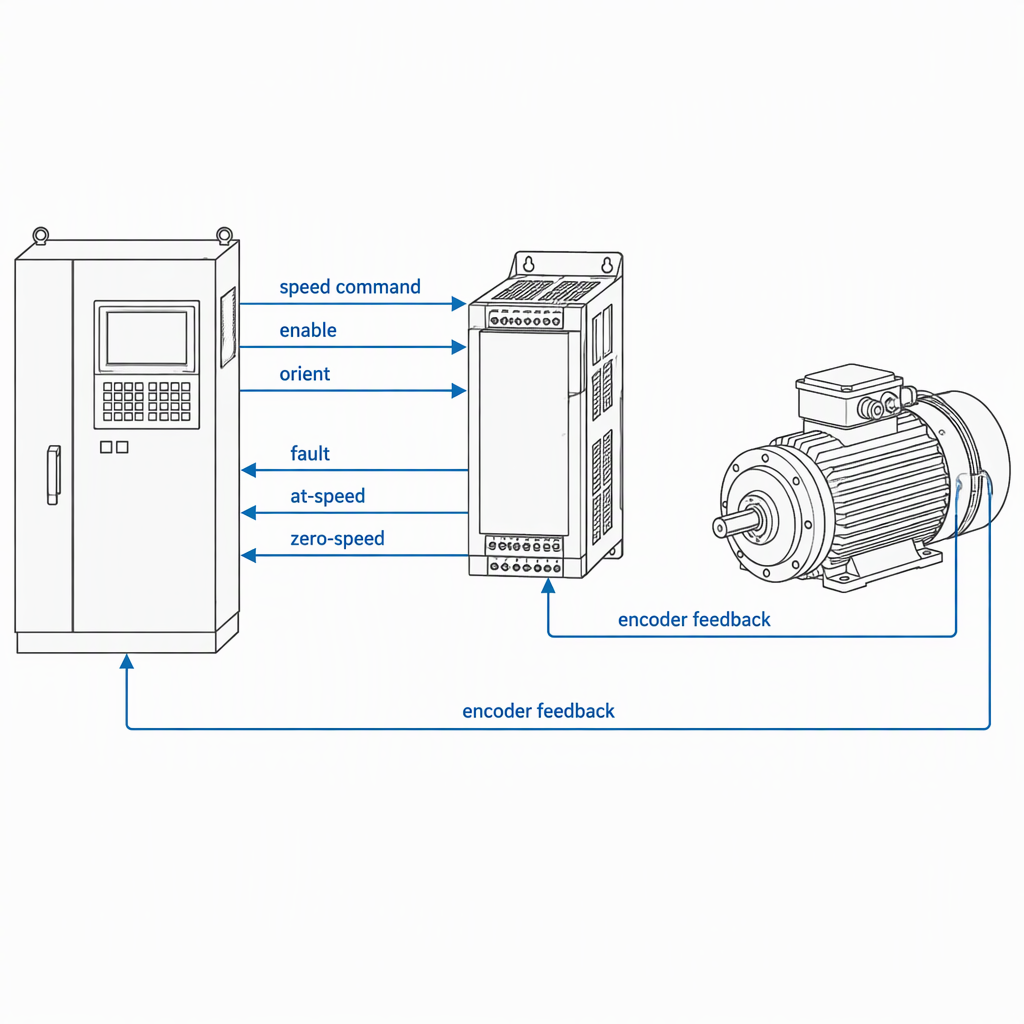
Which signals cross the spindle–controller boundary?
Several separate signal groups cross the boundary between a CNC controller and a spindle drive: the speed command, the enable or run command, the drive's fault or ready return, spindle speed feedback with an optional index pulse, at-speed and zero-speed status, and an orient request with its acknowledgement where the spindle is positioned. Check each group separately, because a spindle can turn correctly while its feedback, interlock or orient channel is still wrong.
| Signal group | Direction | What to confirm | What it decides |
|---|---|---|---|
| Speed command | Controller to drive | Reference form, scaling to speed | Reaching the programmed speed |
| Enable or run | Controller to drive | Level, active state, one or two inputs | Starting when it should not |
| Fault or ready | Drive to controller | Polarity, latching, command drop-out | A faulted drive left commanded |
| Speed feedback | Drive or motor to controller | Interface form, counts per revolution, direction | Constant surface speed, feed per revolution |
| Index pulse | Encoder to controller | Presence, edge, reset behaviour | Synchronised moves, threading |
| At-speed, zero-speed, orient | Drive to controller | Tolerances, delay, acknowledgement, fault input | When feeds, tool changes and orientation start |
One controller that documents its spindle signals individually is LinuxCNC's motion component, whose spindle set covers a speed output and actual speed feedback, at-speed and zero-speed inputs, forward and reverse outputs, a brake output, an orient cycle with acknowledgement and fault input, and the index signals that must reach the spindle encoder for synchronised moves.
How do you verify the speed command path?
Verify the command path in three steps: establish which reference form the drive's speed input accepts, confirm the controller can generate it with enough resolution and a fast enough update for the spindle's speed range, and confirm the scaling between commanded value and resulting speed. An analog or pulse reference drifts and needs trimming; a networked setpoint is exact but bounded by data width and cycle time.
| What you check | Analog or pulse | Networked setpoint |
|---|---|---|
| Scaling and offset | Measure at the drive terminals across the range | Confirm which unit means full speed in the register or object you write; a Modbus master write is limited to 65535 |
| Resolution and update | A software PWM or PDM command has a maximum frequency and a resolution set by how often the generating function runs | Device data sits in a cyclically exchanged process image, so cycle time sets how fast a setpoint arrives |
| Interrupted link | Confirm whether a broken reference reads as zero speed or as a fault | Confirm the controller detects a missing node and the drive has its own configured reaction |
Protocol choice changes the commissioning tools. CANopen carries data over a CAN link specified at the data-link layer by ISO 11898-1 at rates from 10 kbit/s to 1000 kbit/s, and each device publishes its parameters through an object dictionary addressed by 16-bit indexes.
The rate a network achieves depends on its physical design — cabling, length and node count — not only on the nominal maximum; CAN's lower layers are specified in the ISO 11898 series, with high-speed transceivers commonly used up to 1 Mbit/s.
EtherCAT works differently: the main device is the only node allowed to send a frame, and subdevices process frames on the fly in hardware.
Controller ranges differ in the interfaces they offer; SZGH, for example, lists lathe and milling controllers across several axis counts alongside an EtherCAT-based milling controller.
What must be verified on spindle feedback?
Confirm the feedback channel physically and numerically: the encoder interface form the controller accepts, the counts per revolution after controller-side scaling, direction sense, the index pulse's reset behaviour, and whether counting happens in controller hardware or software. A software quadrature counter in a PC-based controller is documented at roughly 10 kHz to 50 kHz depending on the computer, against MHz rates for hardware counters, so compare the pulse rate at maximum spindle speed with that limit before trusting constant surface speed or feed per revolution.
- The encoder interface form matches a controller input — quadrature, a serial interface such as SSI, or a resolver — with error reporting wired back.
- Counts per revolution and position scaling, verified by turning the spindle a known number of revolutions.
- Direction sense, so a positive command counts the way the program expects.
- Index pulse presence, edge and reset, since the index makes a synchronised move repeat each revolution.
- Who closes the loop: a drive that returns only a derived speed leaves the controller unable to detect a real loss of feedback.
How should the enable, fault and at-speed chain be tested?
Force each state instead of waiting for it to occur: command the enable and confirm the spindle turns only while it is present, assert the amplifier-fault input and confirm the controller stops commanding and latches a fault, and confirm the at-speed and zero-speed reports gate the moves that depend on them. Change wiring only with the machine switched off, disconnected from its supply and locked off, and wait the time the drive documentation states before touching a terminal; the forced-state checks themselves are made at control power with the drive output disabled.
| State you force | Expected drive behaviour | Expected controller behaviour | What to check if it differs |
|---|---|---|---|
| Enable removed while turning | Output stage disabled; the spindle coasts or brakes as configured | No further speed command; the program holds or faults | Enable polarity and active level; one input or two |
| Amplifier fault asserted | Output disabled, fault held until reset | Speed command dropped and a fault latched, not merely logged | Normally closed input; how the controller clears the fault |
| At-speed reached | At-speed output asserted within the configured tolerance | The move waiting on at-speed is released | Tolerance setting and signal delay |
| Zero-speed reached | Zero-speed output asserted within tolerance | Tool change or orient cycle permitted | Tolerance setting and time to reach it |
| Orient requested | Spindle orients and the acknowledgement is asserted | Orient-dependent move released; a failed orientation raises the fault input | Orient parameters; whether the fault input is monitored |
A drive commanded through separate forward and reverse inputs still needs the same fault and status chain; its speed is a direction plus a reference, and the speed it reports may be derived rather than measured.
Where does the safety responsibility boundary sit?
Adding a spindle drive or a robot to an existing machine moves the responsibility to whoever puts the modified machine into service. Under EU rules the Machinery Directive 2006/42/EC sets the mandatory essential health and safety requirements, and machinery modified to such an extent that it becomes de facto new machinery is treated like machinery placed on the market for the first time. The Machinery Regulation (EU) 2023/1230 applies on a mandatory basis from 20 January 2027, so plan a long-running retrofit around that date.
The legal position, the scope that brings substantially modified machinery back within the directive and the transition dates are published on the European Commission's machinery legislation page.
Safety data can also travel inside the ordinary cyclic process data — the EtherCAT safety container is one example — so targeted parts of a machine can be brought to a standstill. That is a transport capability, not a substitute for the machine's own safety circuit: device conformance testing shows the device implements the protocol and says nothing about the risk assessment of the machine it is built into.
Which utilities, space and wiring checks belong in the plan?
Work from the documentation of the exact drive frame you are installing, not from a series listing or catalogue page. Confirm supply voltage, phase count and rated input current, the heat dissipated inside the enclosure and the clearance the manual requires, cooling method and airflow path, the braking or regeneration arrangement and where its resistor is mounted, motor and encoder cable types, the separation of power and signal routing, and the earthing and shielding scheme.
- Supply voltage, phases and rated input current for the exact frame, from its manual.
- Heat dissipated inside the enclosure, clearance to other components, and access for filters and fans.
- Cooling method and airflow path, including where the drive's own fans discharge.
- Braking or regeneration arrangement: whether a braking resistor is needed, its rating and mounting position.
- Motor cable type, cross-section and length limits, and whether a shielded motor cable is required.
- Encoder cable routing, kept away from motor and power conductors, with the shield terminated as the documentation specifies.
- Earth and bonding for panel, machine frame and spindle motor, and the single point where shields terminate.
- Space for cable bends, the encoder connector, and the drive's keypad or service port.
Power class sets how much of this matters. SZGH's own S4T spindle servo drive series is listed from 1.5 kW to 132 kW, with separate pages for individual ratings, and a small frame and a large frame in one series do not share the same supply, cable or cooling requirements. Take every value from the frame you are installing.
What is a safe first-run sequence for a new spindle connection?
Energise in stages and stop at the first result that disagrees with the documentation: verify the wiring with the machine isolated, test the signals at control power with the drive output disabled, rotate unloaded at low speed, check the feedback count and index, force the interlocks and the stop, then run under load. Before any manual access to terminals or the motor junction box, switch the machine off at its main disconnect, disconnect it from the supply, lock it off, and wait the time the drive documentation states before touching conductors.
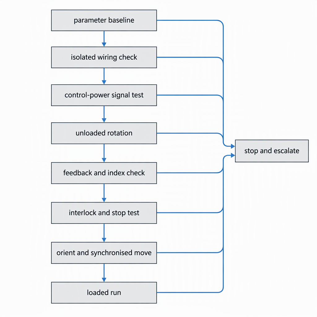
- Record the baseline: the drive's parameter set, the controller's spindle configuration (gear ratios, minimum and maximum speed, at-speed and zero-speed tolerances) and the current value of every parameter you intend to change.
- Isolate and inspect: switch off, disconnect and lock off the supply, wait the stated time, then compare every connection with the drawing — motor phases, encoder channels, command reference, enable, fault and brake.
- Control power only, output disabled: confirm the commanded value, the enable state and the fault reporting before rotation is possible, and check the value reaching the drive across the range.
- Unloaded rotation at low speed in each direction: confirm direction, reported speed and the assertion of at-speed.
- Feedback check: turn the spindle a known number of revolutions and compare the reported position, confirm direction sense, and confirm the index resets the count once per revolution.
- Interlock and stop test: remove the enable, assert the drive fault, and operate the emergency stop from every station; confirm the spindle stops and the controller drops its speed command.
- Loaded run with the real tool and workpiece load: confirm the commanded speed holds and the drive stays within its limits.
- Baseline parameters and every change recorded.
- At-speed and zero-speed tolerances set for this spindle, not left at defaults.
- Maximum speed, gear ratios and position scaling verified against a known rotation.
- Emergency stop tested from every station, and the drive alarm log read and cleared.
How does adding a robot change what you verify?
A robot loading parts into the same spindle adds a second controller that must not command the spindle while the CNC does. Verify the handshake as a mutual-exclusion interlock: exactly one controller holds the right to start and stop the spindle at any moment, the handover is confirmed by explicit signal exchange rather than timing assumptions, and the robot side reads at-speed and zero-speed before entering the transfer position.
Combined cells are sometimes supplied with both controllers from one manufacturer: SZGH states that it develops and manufactures its own CNC controllers, servo drives, servo motors and robot controllers, and integrates CNC machines with industrial robot arms into combined cells. Even then, mutual exclusion has to be designed and tested rather than assumed.
Conclusion
The link between a spindle and a CNC controller is proven in stages, not at the moment the motor first turns. Work through the signal map, the command representation, the feedback scaling, the enable and fault chain, the utilities and the safety responsibility boundary in that order, and stop at the first check that disagrees with the documentation.
- Every spindle connection carries several separate signal groups; a working speed command does not prove the feedback, interlock or orient channel.
- Verify the command representation and its scaling at the drive, not only in the controller configuration.
- Compare the encoder pulse rate at maximum spindle speed with the controller's counting limit before relying on constant surface speed.
- Force the enable, fault, at-speed and stop states instead of waiting for them to occur.
- A modified machine can become de facto new machinery, and the conformity obligation sits with whoever puts it into service.
- Where a robot shares the spindle, make the right to command it mutually exclusive and prove it.
Frequently asked questions
These are the questions that most often settle a spindle-and-controller pairing before the panel is wired.
Does a drive profile such as CiA 402 or a fieldbus conformance certificate guarantee the drive will work with my controller?
No. A profile describes a standardised object set that the drive exposes through its object dictionary, so it tells you the vocabulary is standard, not that both sides use the same objects, units and scaling.
A conformance test shows the device implements the protocol. Neither covers the enable, fault, at-speed or orient signals, which are usually discrete wiring, so confirm the setpoint object, its unit and its scaling against your own controller configuration.
Does a spindle need an encoder or an index pulse, for example for threading or orient?
An encoder is not required to make a spindle turn, but it is required for anything the controller must synchronise or position: the index and revolution signals must reach the spindle encoder, and an orient cycle needs an acknowledgement and a fault input.
A drive commanded through separate forward and reverse inputs can run with no feedback at all, and the controller then simulates the speed it cannot measure. Constant surface speed, feed per revolution and synchronised moves stay unavailable in that configuration.
What are the at-speed, zero-speed and orient signals used for during commissioning?
They report that the spindle has reached a commanded condition, and they gate the operations that depend on it. At-speed releases the feed moves waiting on it, zero-speed permits a tool change or orient cycle, and the orient acknowledgement reports that the spindle reached its position, with a separate fault input for a failed orientation. Set the tolerances for the actual spindle and confirm when each signal appears.
Does a safe-torque-off input or a fieldbus safety protocol remove the need for an external safety circuit?
Not by itself. A fieldbus safety container lets safety data travel inside the ordinary cyclic process data so targeted parts of a machine can be brought to a standstill, but that is a transport capability, not a decision about which functions the machine needs.
Treat a safe-torque-off input as one element inside a safety function, and take the functions and their required performance from the machine's risk assessment.
How do I check whether the controller can count my encoder at full spindle speed?
Work out the pulse rate first: pulses per revolution, multiplied by the quadrature count mode, multiplied by maximum spindle speed in revolutions per second. A software quadrature counter in a PC-based controller is documented at roughly 10 kHz to 50 kHz depending on the computer, so a modest encoder can exceed a software limit at high speed. Compare the calculated rate with the limit documented for your controller input.
How do I confirm the drive and controller agree on command scaling?
Measure rather than assume. For a networked setpoint, confirm the engineering unit that represents full speed in the register or object you write; a value written through a Modbus master component is limited to 65535, so the unit and the scaling have to be chosen deliberately.
For an analog or pulse reference, measure the value at the drive across the commanded range and check the offset.


